| Availability: | |
|---|---|
| Quantity: | |
CI12A / CI18A / CI30A
GWIEC
CI12A, CI18A and CI30A provide continuous distance-related voltage or current signals. Choose the required 0–10 V, 10–0 V, 0–20 mA, 4–20 mA or combined output, then match the mounting and load.
| Outward appearance code | GI12A | GI18A | ||
| Installation | Flush | Non-flush | Flush | |
| Detection distance | 2 mm ±10% | 4 mm ±10% | 5 mm ±10% | |
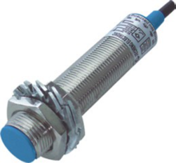
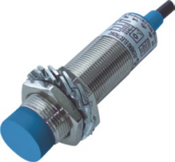
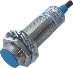
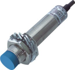
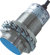
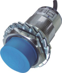
| Product photograph | View original image CI12A flush product photograph | View original image CI12A non-flush product photograph | View original image CI18A flush product photograph | |
| Voltage type | 0–10 V voltage | CI12A-02U | CI12A-04U | CI18A-05U |
| 10–0 V voltage | CI12A-02U2 | CI12A-04U2 | CI18A-05U2 | |
| Current type | 0–20 mA current | CI12A-02I | CI12A-04I | CI18A-05I |
| 4–20 mA current | CI12A-02I4 | CI12A-04I4 | CI18A-05I4 | |
| Voltage + current | 0–10 V + 0–20 mA combined | CI12A-02IU | CI12A-04IU | CI18A-05IU |
| Technical parameters | ||||
| Set distance | 0–1.7 mm | 0–4 mm | 0–4 mm | |
| Standard target | SPCC steel 12 x 12 x 1 mm | SPCC steel 15 x 15 x 1 mm | SPCC steel 18 x 18 x 1 mm | |
| Supply voltage | 10–30 V DC | 10–30 V DC | 10–30 V DC | |
| Switching point tolerance | ±10% | ±10% | ±10% | |
| Load / output requirement | Voltage output RL ≥4.7 kΩ | Current output RL ≥470 Ω | Voltage output RL ≥4.7 kΩ | |
| Voltage drop | <2.5 V | <2.5 V | <2.5 V | |
| Consumption current | <10 mA | <10 mA | <10 mA | |
| Hysteresis | 1–20% | 1–20% | 1–20% | |
| Repeatability | <3% | <3% | <3% | |
| Switching frequency | 200 Hz | 200 Hz | 200 Hz | |
| Indicator | Red LED | Red LED | Red LED | |
| Reverse polarity protection | Yes | Yes | Yes | |
| Surge protection | Yes | Yes | Yes | |
| Short circuit protection | Yes | Yes | Yes | |
| Ambient temperature | −25 to +70 °C | −25 to +70 °C | −25 to +70 °C | |
| Ambient humidity | 35–95% RH | 35–95% RH | 35–95% RH | |
| Protection rating | IP67 | IP67 | IP67 | |
| Housing material | Nickel-plated brass | Nickel-plated brass | Nickel-plated brass | |
| Connection | 2 m PUR cable; M8 connector option shown | 2 m PUR cable; M8 connector option shown | 2 m PUR cable; M8 connector option shown | |
| Catalog marking | CE symbol shown in catalog | CE symbol shown in catalog | CE symbol shown in catalog | |
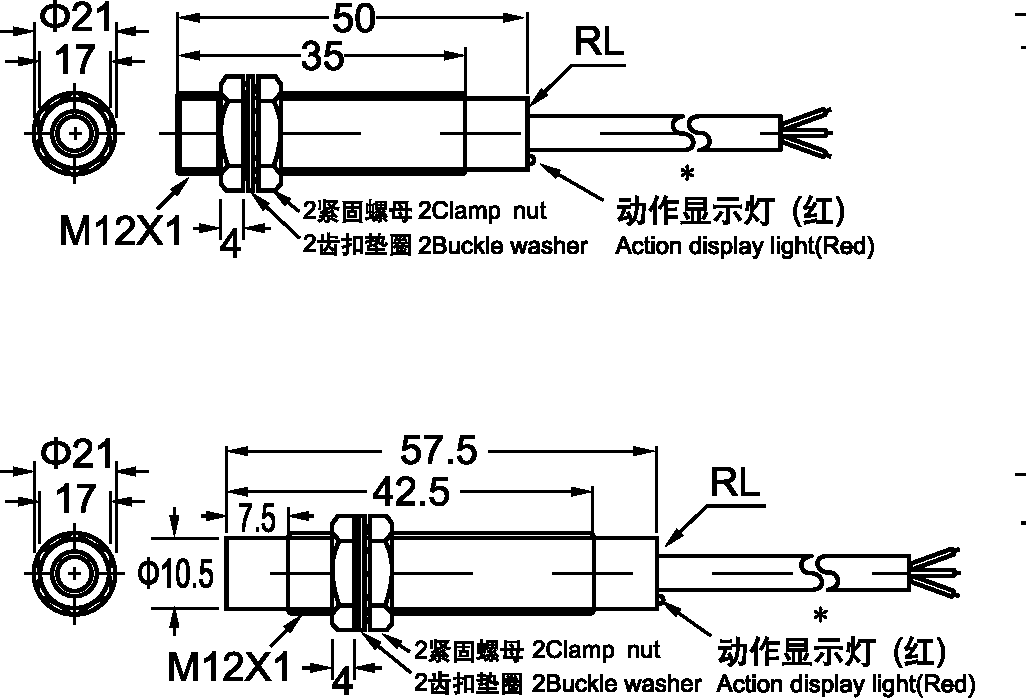
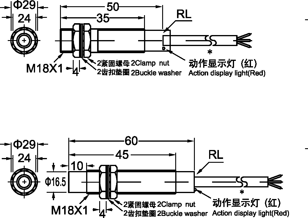
| Engineering drawing Click to enlarge | View original image CI12A / CI18A — group 1 engineering drawing | View original image CI12A / CI18A — group 1 engineering drawing | ||
| Outward appearance code | GI18A | GI30A | ||
| Installation | Non-flush | Flush | Non-flush | |
| Detection distance | 8 mm ±10% | 10 mm ±10% | 15 mm ±10% | |
| Product photograph | View original image CI18A non-flush product photograph | View original image CI30A flush product photograph | View original image CI30A non-flush product photograph | |
| Voltage type | 0–10 V voltage | CI18A-08U | CI30A-10U | CI30A-15U |
| 10–0 V voltage | CI18A-08U2 | CI30A-10U2 | CI30A-15U2 | |
| Current type | 0–20 mA current | CI18A-08I | CI30A-10I | CI30A-15I |
| 4–20 mA current | CI18A-08I4 | CI30A-10I4 | CI30A-15I4 | |
| Voltage + current | 0–10 V + 0–20 mA combined | CI18A-08IU | CI30A-10IU | CI30A-15IU |
| Technical parameters | ||||
| Set distance | 0–8 mm | 0–8 mm | 0–18 mm (catalog; confirm) | |
| Standard target | SPCC steel 30 x 30 x 1 mm | SPCC steel 30 x 30 x 1 mm | SPCC steel 54 x 54 x 1 mm | |
| Supply voltage | 10–30 V DC | 10–30 V DC | 10–30 V DC | |
| Switching point tolerance | ±10% | ±10% | ±10% | |
| Load / output requirement | Current output RL ≥470 Ω | Voltage output RL ≥4.7 Ω (printed; confirm) | Current output RL ≥470 Ω | |
| Voltage drop | <2.5 V | <2.5 V | <2.5 V | |
| Consumption current | <10 mA | <10 mA | <10 mA | |
| Hysteresis | 1–20% | 1–20% | 1–20% | |
| Repeatability | <3% | <3% | <3% | |
| Switching frequency | 200 Hz | 200 Hz | 200 Hz | |
| Indicator | Red LED | Red LED | Red LED | |
| Reverse polarity protection | Yes | Yes | Yes | |
| Surge protection | Yes | Yes | Yes | |
| Short circuit protection | Yes | Yes | Yes | |
| Ambient temperature | −25 to +70 °C | −25 to +70 °C | −25 to +70 °C | |
| Ambient humidity | 35–95% RH | 35–95% RH | 35–95% RH | |
| Protection rating | IP67 | IP67 | IP67 | |
| Housing material | Nickel-plated brass | Nickel-plated brass | Nickel-plated brass | |
| Connection | 2 m PUR cable; M8 connector option shown | 2 m PUR cable; M8 connector option shown | 2 m PUR cable; M8 connector option shown | |
| Catalog marking | CE symbol shown in catalog | CE symbol shown in catalog | CE symbol shown in catalog | |
| Engineering drawing Click to enlarge | View original image CI18A / CI30A — group 2 engineering drawing | View original image CI18A / CI30A — group 2 engineering drawing | ||
Selection note: The family headings use GI12A/GI18A/GI30A but the model rows use CI. The CI30A non-flush set-distance cell says 0–18 mm against a 15 mm nominal rating. The load row prints ≥470 Ω for current-related columns; confirm the actual receiver load requirement and output circuit before connection.
Values are transcribed from the GWIEC sensor catalog, pages 24, 26. A dash means no model is listed in that source cell. Nominal distance and an operating/set distance are different quantities. Select the complete model, output, supply, connection and mounting dimensions together.
Click any product photograph or engineering drawing to open the original image at full size.
Compare analog sensor families · All proximity sensor categories · Contact GWIEC for model confirmation