GWIEC SENSOR GUIDE
Proximity Switches: Basic Parameters and Electrical Characteristics
Working principles, technical terms, installation, electrical connections, precautions, applications and model-code interpretation from catalog pages 01–08.
CATALOG 01
Proximity Switch Working Principle
Proximity switches, also called proximity sensors, include inductive, capacitive, analog, Hall-effect and magnetic types. They can be used with PLCs, microcontrollers, logic circuits, electronic counters, solid-state relays and small relays.
Inductive proximity sensors
An inductive proximity sensor contains a high-frequency oscillator, detector, amplifier, trigger and output circuit. The oscillator creates an alternating electromagnetic field at the sensing face. As a metal target approaches, eddy currents in the metal absorb oscillator energy and reduce or stop oscillation. The oscillating and non-oscillating states are converted into a binary switching signal, amplified and delivered by the output stage.
Capacitive proximity sensors
A capacitive proximity sensor contains a high-frequency oscillator and amplifier. The sensing face and earth form part of a capacitor in the oscillating circuit. The circuit initially remains in a non-oscillating state. When a target approaches, its capacitance changes and the oscillator starts. These two states are converted into a binary switching signal through the amplifier.
Analog sensors
An analog sensor, also called a linear displacement sensor, produces an electrical output that changes in a linear relationship with the distance of a metal target from its sensing face. This signal can be used for monitoring.
Hall-effect sensors
A Hall-effect proximity sensor contains a Hall integrated circuit. The Hall effect converts the presence or absence of a magnetic field into a switching signal. Applications include signal detection and automatic control.
Magnetic sensors
A magnetic sensor contains a reed switch and an amplifier. An approaching external magnetic field magnetizes and operates the reeds. The amplifier increases the switching capability to control an external circuit.
CATALOG 01–02
Proximity Switch Technical Terms
● Operating distance
Operating distance is a principal proximity-switch parameter. It mainly depends on the sensing-face diameter; target material and ambient temperature also affect it. For magnetic and Hall-effect sensors, an iron mounting plate and magnetic-field strength can also affect operating distance. Targets may approach axially or radially; axial approach is generally used.
● Rated sensing distance (Sn)
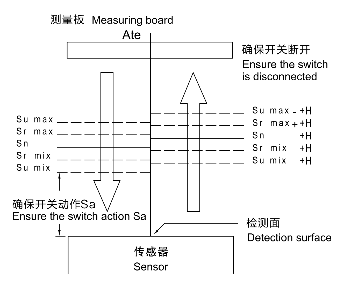
A standard nominal value that does not include external environmental influences.
● Standard detection target
A smooth ST37 steel square, 1 mm thick, with a side length of 3 × Sn. Changes in target dimensions or material reduce the sensing range relative to this reference.
● Effective operating distance (Sr)
The distance measured at rated supply voltage and room temperature of 23 ±5 °C: 0.9 Sn ≤ Sr ≤ 1.1 Sn.
● Usable operating distance (Su)
The distance measured over the permitted ambient-temperature range of -25 to +70 °C and from 85% to 110% of rated input voltage: 0.9 Sr ≤ Su ≤ 1.1 Sr.
● Assured operating distance (Sa)
Within this range, operation with the measuring target is reliable: 0 ≤ Sa ≤ 0.81 Sn.
● Repeatability (R)
The variation in effective operating distance measured over 8 hours at an ambient temperature of 23 ±5 °C, with uncontrolled relative humidity and a supply of Ue ±5 as printed in the catalog: R ≤ 0.1 Sn. The source does not state a unit after the ±5 supply tolerance; confirm the applicable specification.
● Assured switch-off distance
The catalog describes the switch as disconnected when the separation between the target and sensing face is greater than the rated operating distance. The original distance diagram below distinguishes the sensing-distance bands and hysteresis.
● Attenuation
The attenuation coefficient expresses the reduction in operating distance for a material relative to the ST37 steel reference target. For inductive switches, target conductivity is an important influence.
Inductive sensors: material attenuation coefficients
| Material | Attenuation coefficient |
| Steel | 1.0 |
| Stainless steel | 0.85 |
| Aluminum | 0.4 |
| Brass | 0.4 |
| Copper | 0.3 |
Capacitive sensors: material attenuation coefficients
| Material | Attenuation coefficient |
| Steel | 1.0 |
| Stainless steel | 1.0 |
| Aluminum | 0.75 |
| Brass | 0.6 |
| Copper | 0.45 |
● No-load current (I0)
Current consumed by the proximity switch when no load is connected.
● Operating current (IL)
The maximum load current during continuous operation.
● Momentary current (IK)
The current permitted for a short interval while the switch is closed without damaging the switch.
● Residual current (IR)
Current flowing through the load while the switch is in its off state.
● Operating voltage (UB)
The minimum-to-maximum supply-voltage range within which the switch operates as specified.
● Voltage drop (UD)
The voltage measured across the switch when it is turned on.
● Operating frequency (F)
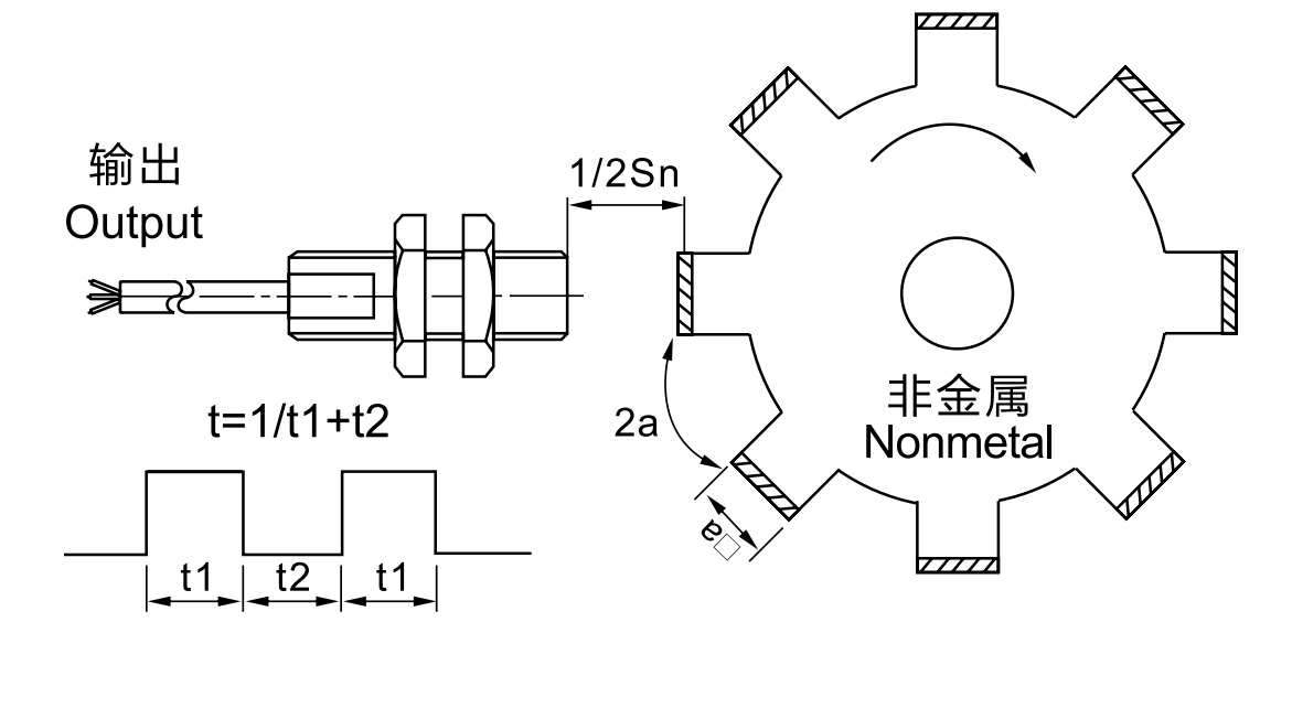
The maximum switching rate between attenuated and non-attenuated states, expressed in hertz (Hz).
CATALOG 03
Proximity Switch Installation Method
Cylindrical proximity switches
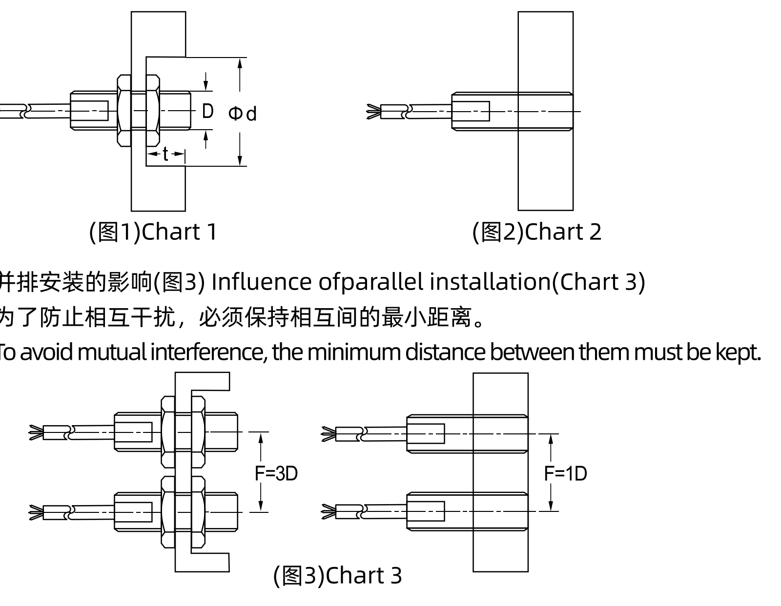
A non-flush, unshielded sensor can obtain a larger operating distance, related to its diameter. To prevent surrounding metal from influencing operation, maintain clearance around the sensing head as shown in Figure 1.
Internal shielding reduces the lateral magnetic field of a flush sensor. The catalog gives an approximate sensing distance of 60% of the corresponding unshielded type and shows the sensor installed flush in metal in Figure 2. Magnetic sensors are described as unaffected by the mounting condition provided the surrounding material is not magnetized.
Figure 3 shows parallel-installation spacing to reduce mutual interference. The cylindrical examples indicate F = 3D for non-flush sensors and F = 1D for flush sensors. Refer to the instructions for the exact model and mounting conditions.
Angular and square sensor mounting requirements
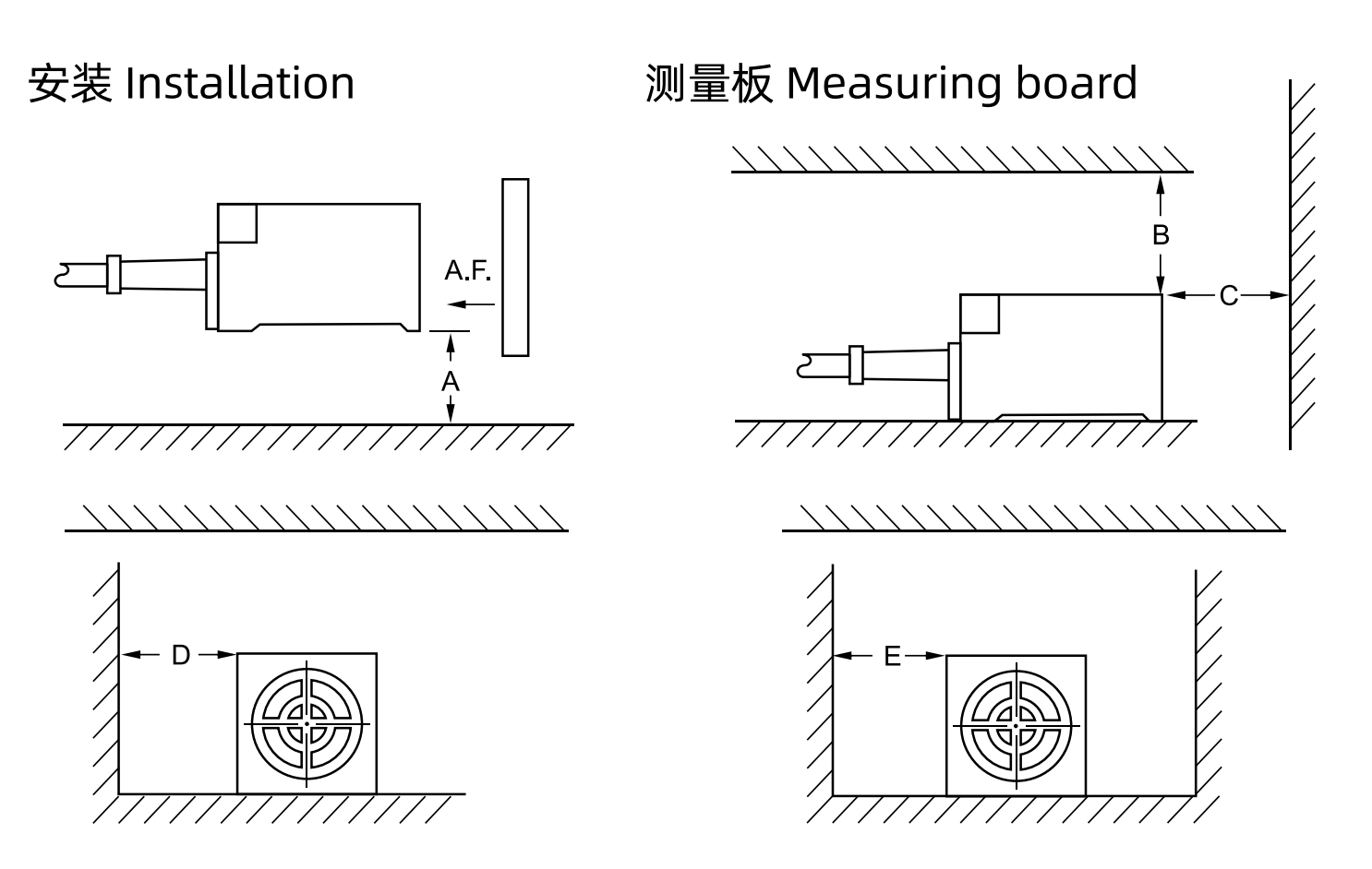
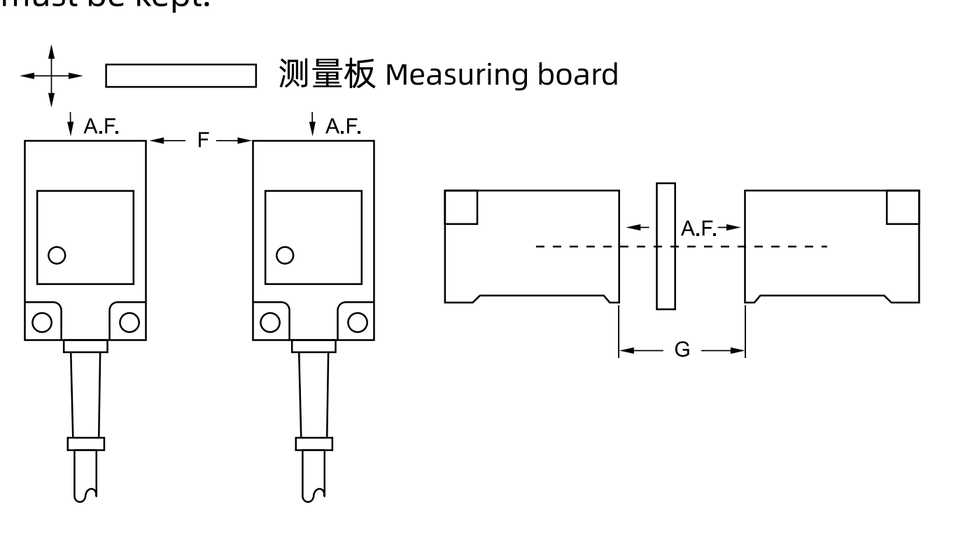
Maintain the clearances indicated by A, B, C, D and E. The measuring board represents the detection target. Refer to the model-specific operating instructions for dimensions.
Parallel installation of rectangular sensors
Maintain the illustrated minimum separation to avoid mutual interference. F and G identify spacing in the original drawing; model-specific instructions provide the corresponding values.
CATALOG 03–04
Proximity Switch Output Methods and Electrical Characteristics
Connection between a proximity switch and a PLC
The catalog illustrates a DC three-wire NPN output connected to a programmable-controller DC input module.
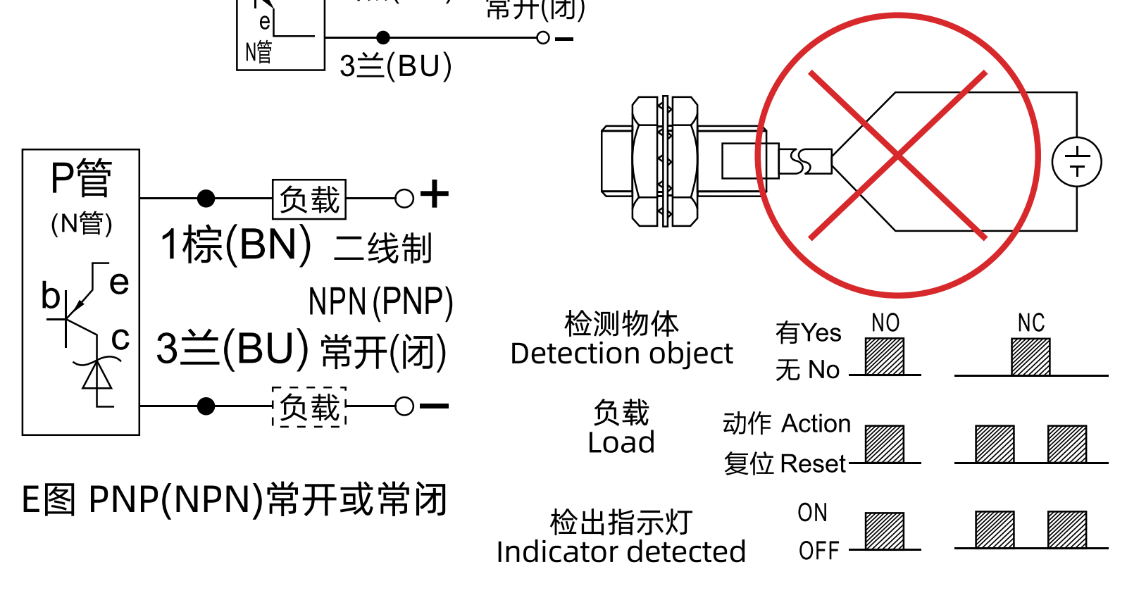
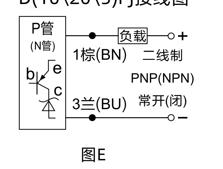
DC two-wire system: NO or NC
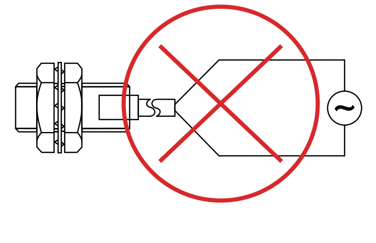
Connect the sensor in series with the load. Do not connect a two-wire sensor directly across the power supply. The catalog describes polarity protection, a small leakage current in the open state and a voltage drop across the switching element in the closed state.
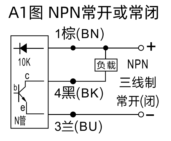
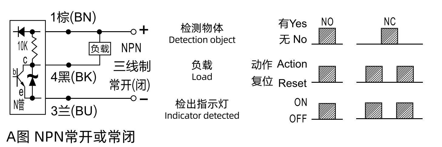
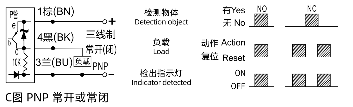
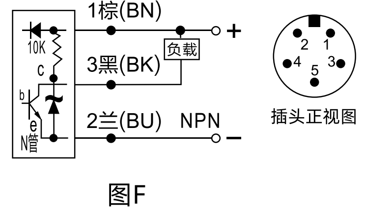
DC three-wire system: NPN or PNP, NO or NC
The load and supply are connected separately. The catalog describes reverse-polarity, short-circuit and overload protection, with residual current small enough to neglect in this description.
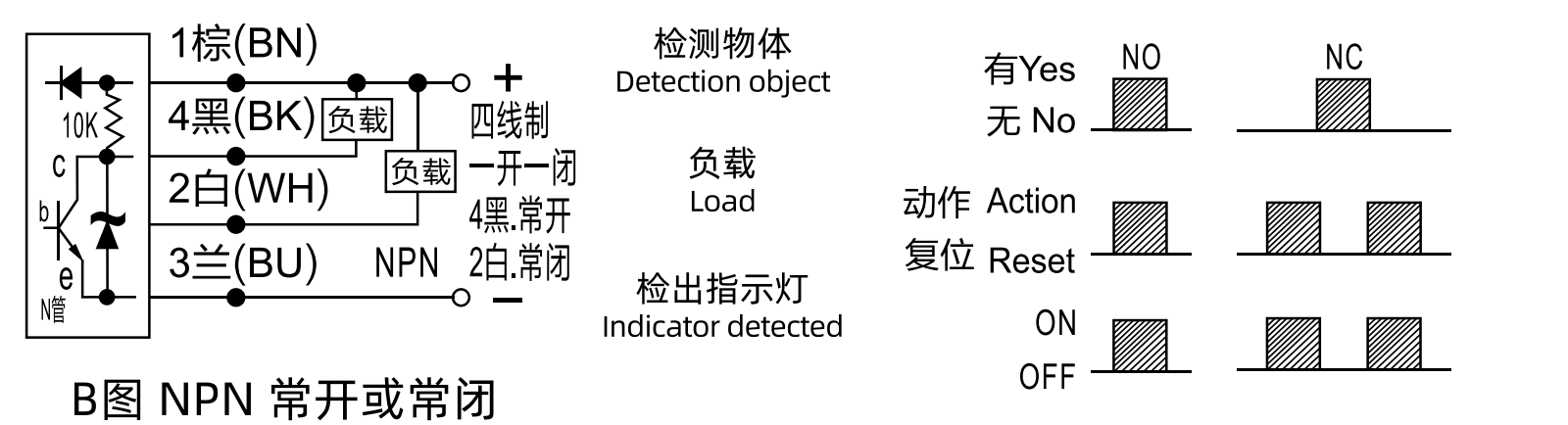
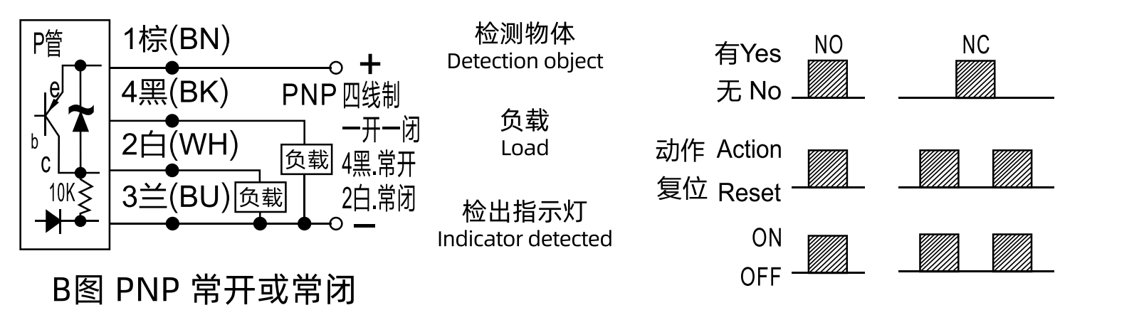
DC four-wire system: NPN or PNP, NO and NC
The sensor provides two output states: normally open and normally closed. Keep the wire colors and terminal assignments shown in the selected circuit.
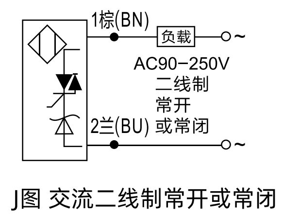
AC two-wire system: NO or NC
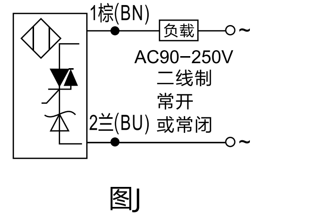
Connect the sensor in series with its load, never directly across the supply. A small leakage current remains in the open state; the switching element has a small voltage drop when closed.
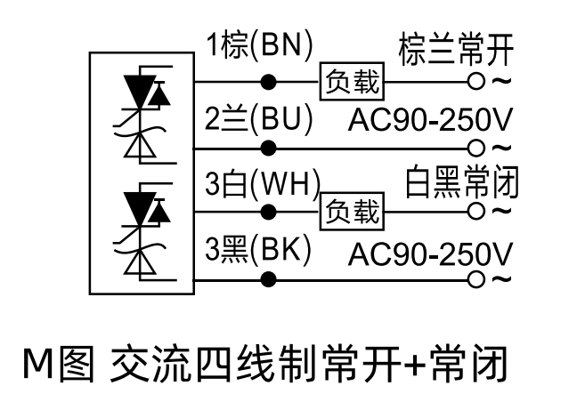
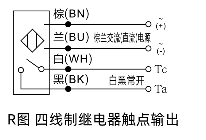
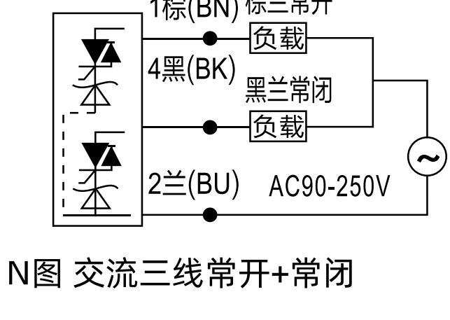
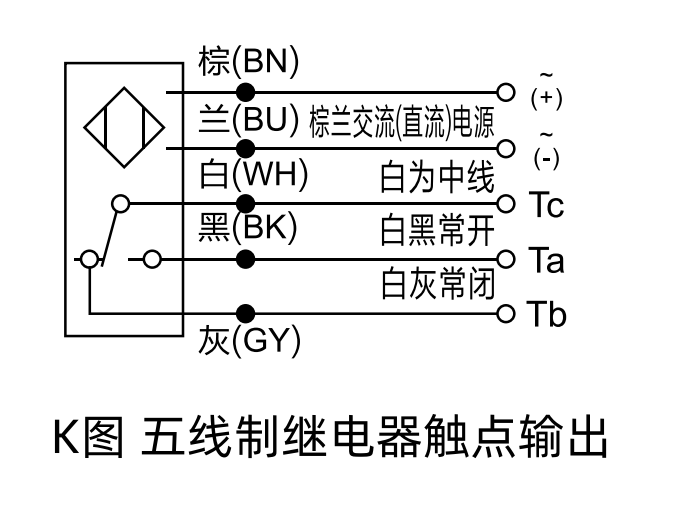
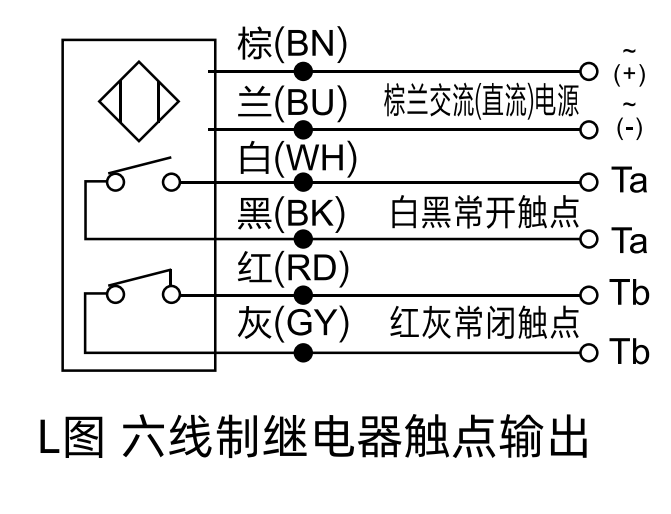
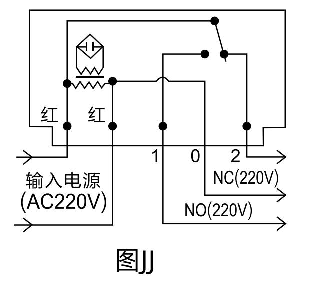
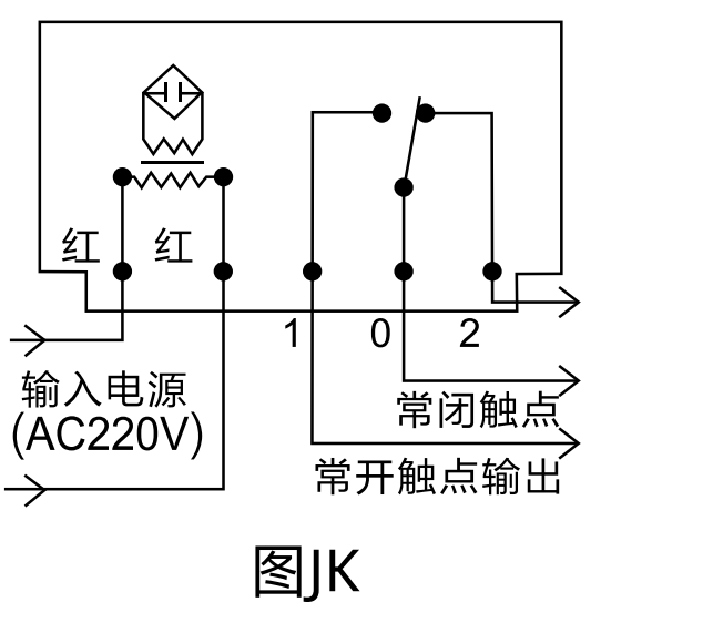
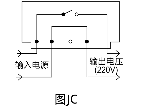
Relay contact and AC output connection diagrams
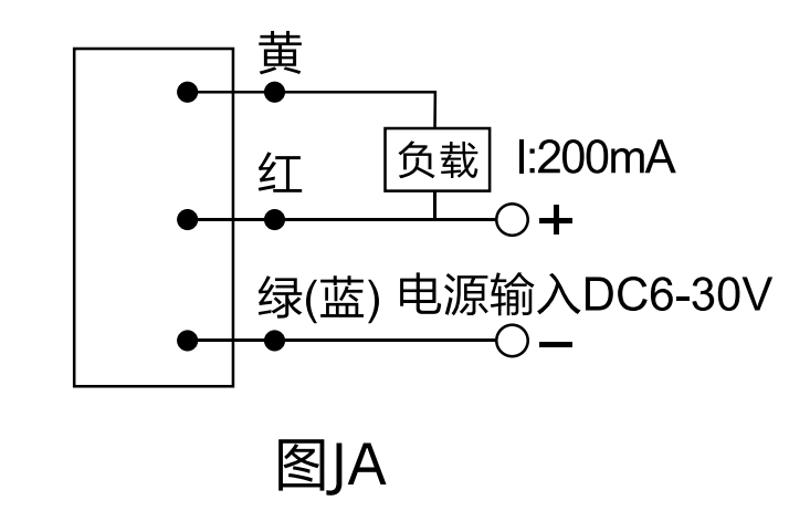
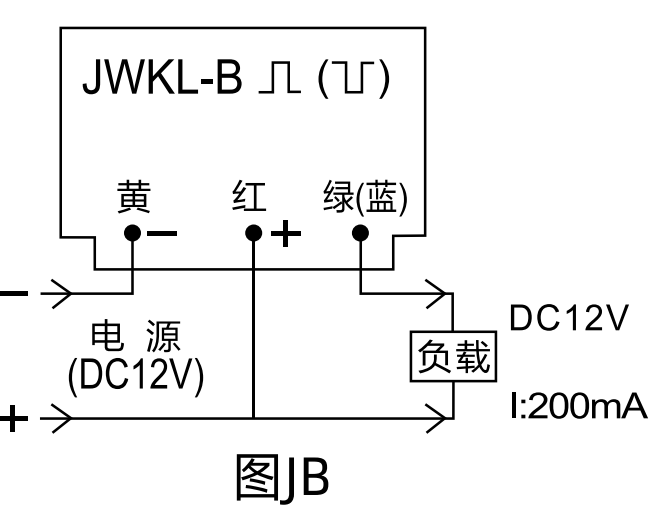
Connector and special-model wiring diagrams
Diagram legend: BN = brown; BK = black; WH = white; BU = blue; RD = red; GY = gray. NO = normally open; NC = normally closed. The original drawings retain their terminal numbers, Chinese labels and bilingual switching-state annotations; the English captions identify each circuit.
CATALOG 05
Series and Parallel Connection of Proximity Switches
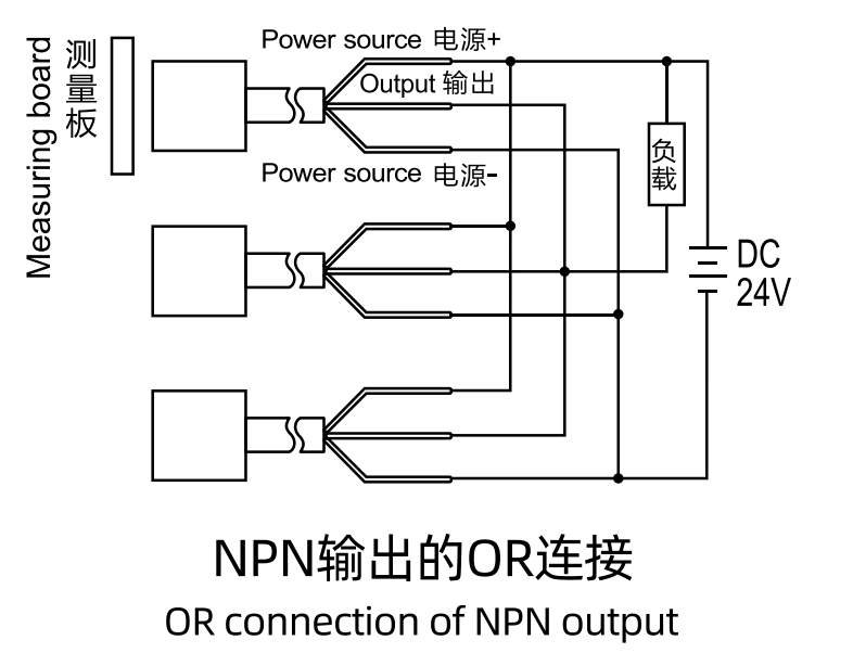
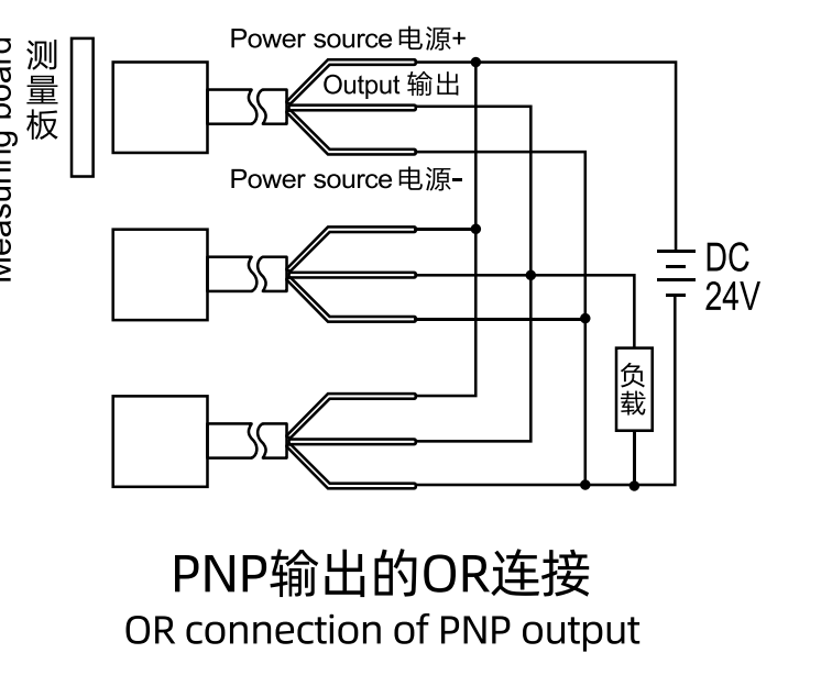
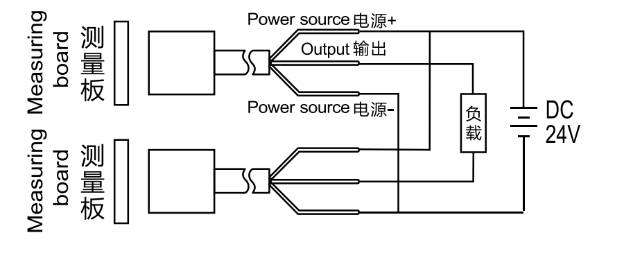
OR connection: parallel outputs
Any one active sensor can drive the load. The permissible number of parallel sensors depends on the sum of their leakage currents and whether that current affects load operation. Do not mix NPN and PNP types in this OR connection. The Chinese source states this restriction; the printed English sentence says the opposite.
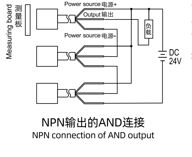
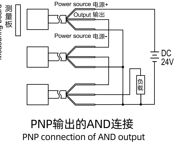
AND connection: series outputs
The load is driven only when all connected sensors operate. The permissible number of sensors depends on the sum of their saturation-voltage drops and the supply voltage remaining available to each sensor. The catalog describes the response as including the accumulated initialization/reset delays of the connected sensors.
Illustrated mixed NPN/PNP series arrangement
The source separately illustrates an AND series circuit using NPN and PNP outputs. Follow the specific illustrated arrangement and the exact model instructions; the OR restriction above must not be reversed by the catalog’s English wording.
CATALOG 05–06
Proximity Switch Precautions
Cautions when connecting or disconnecting the power supply
When the switch is connected to a counter or PLC with an internal initialization/reset circuit, the source describes no normal initialization problem. Avoid the following conditions: a target close to the switching distance during power-on or power-off; a sharp rise or fall in the circuit time constant for DC voltage-output or DC switching types; or oscillation and noise when current is made or broken in an AC switching type.
Capacitive and lamp loads
Do not directly connect a load with a large inrush current, such as a capacitor or lamp. Use the relay connection or a series current-limiting resistor described in the source. Choose the current limit within the sensor’s load-current rating and connect it through the load.
The original expressions relate supply voltage, permitted peak-load current, limiting resistance R and allowable resistor power. The figure prints resistance in kΩ; verify consistent units and the exact model ratings before selecting components.
Installation precautions
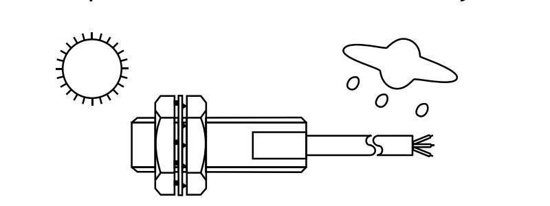
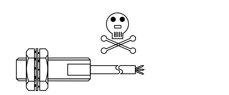
1. Outdoor exposure
Do not use the switch exposed outdoors without protection; fit a protective cover where necessary.
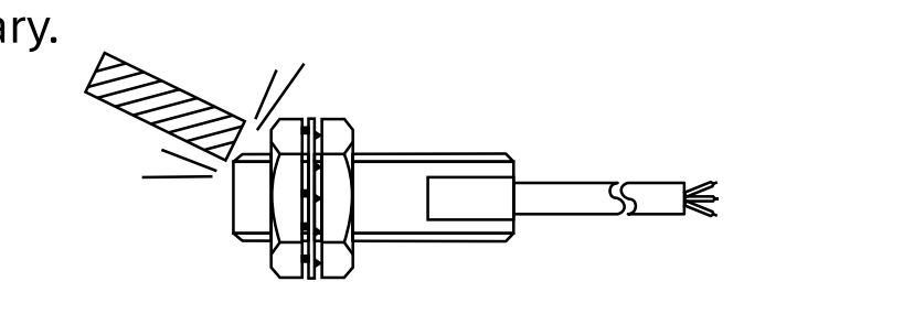
2. Impact on the sensing face
Do not strike the sensing face with hard objects. Use a protective cover where required.
3. Corrosive conditions
Do not use the sensor in an environment containing corrosive substances.
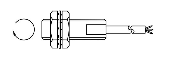
4. Fastening
Do not tighten with excessive force. Use a spring washer when fastening as illustrated.
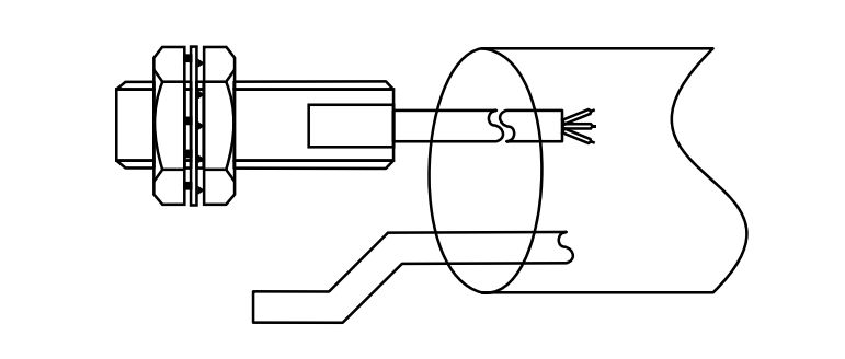
5. Cable routing
Route sensor wiring in its own metal flexible conduit. Do not put it in the same conduit as power or motor wiring.
6. Cable tension
Do not pull the proximity-switch cable with excessive force.
CATALOG 06
Application Examples
Inductive sensors are used in aviation, aerospace and industrial production. The source describes their use for conductive targets, or targets fixed to a metal object, where their switching response, interference resistance, application range and cost suit the task.
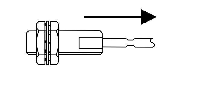
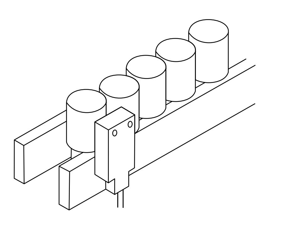
1. Detecting screws on magnetic tape
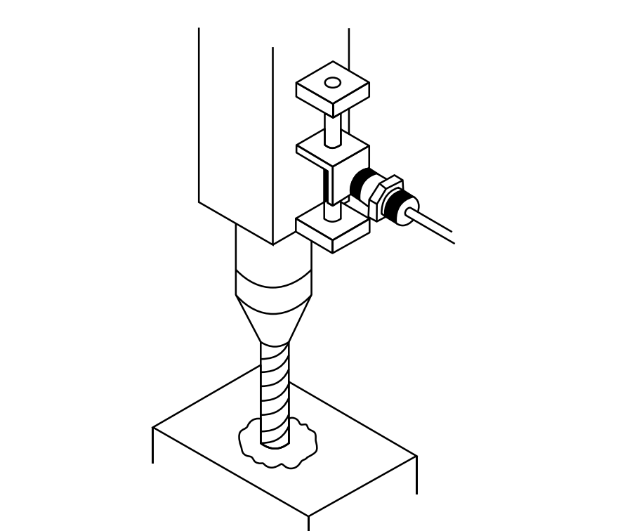
2. Controlling drilling depth
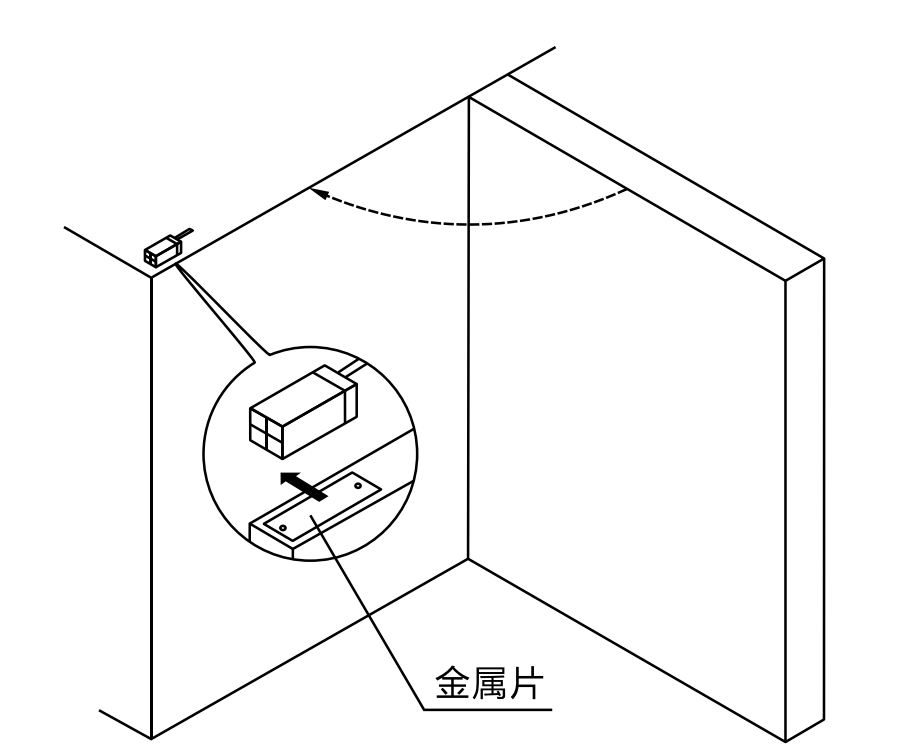
3. Detecting door opening and closing
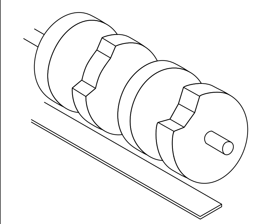
4. Detecting cam position
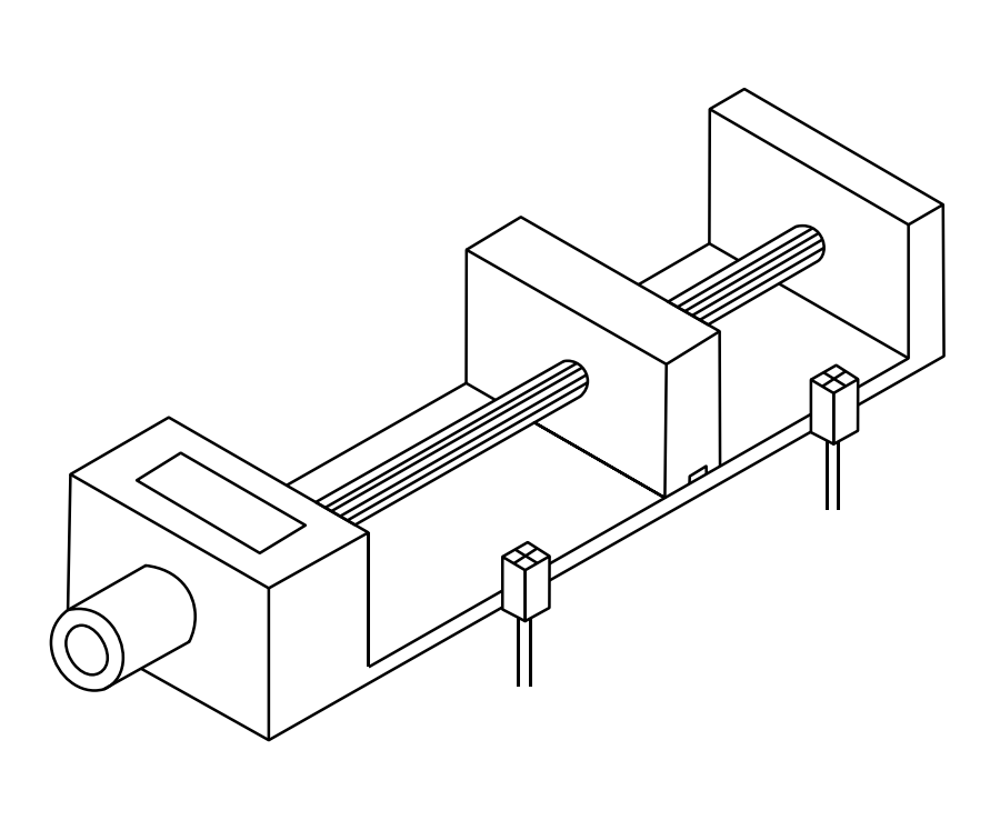
5. Monitoring worktable overspeed
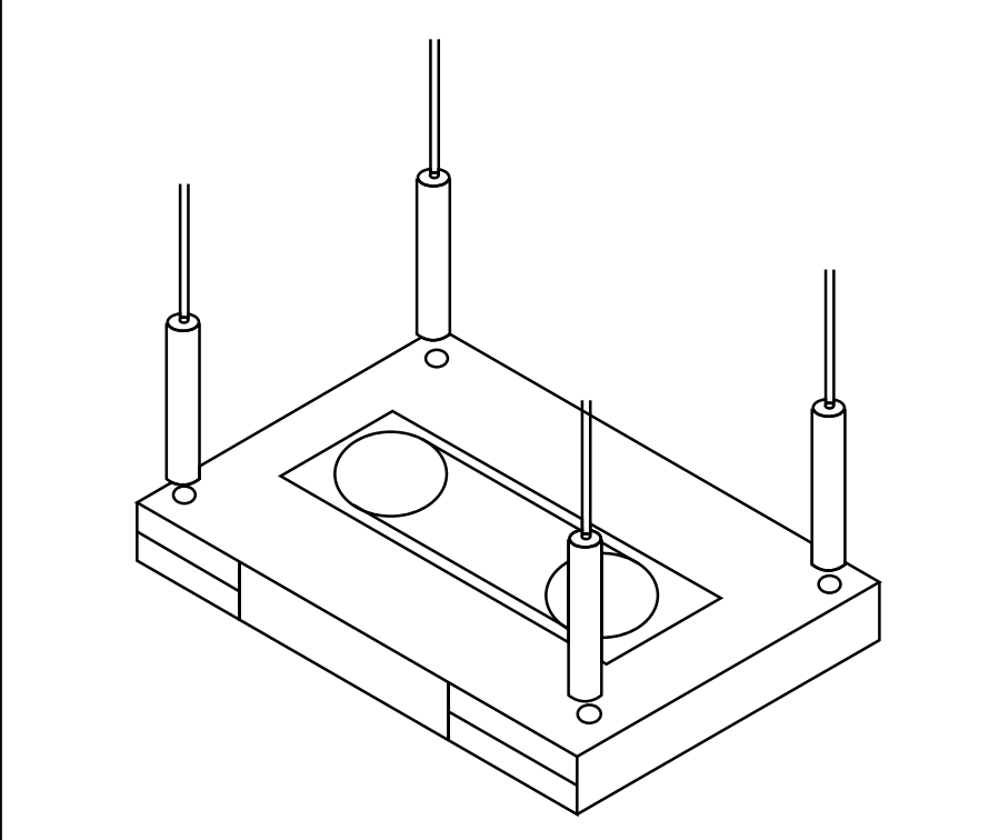
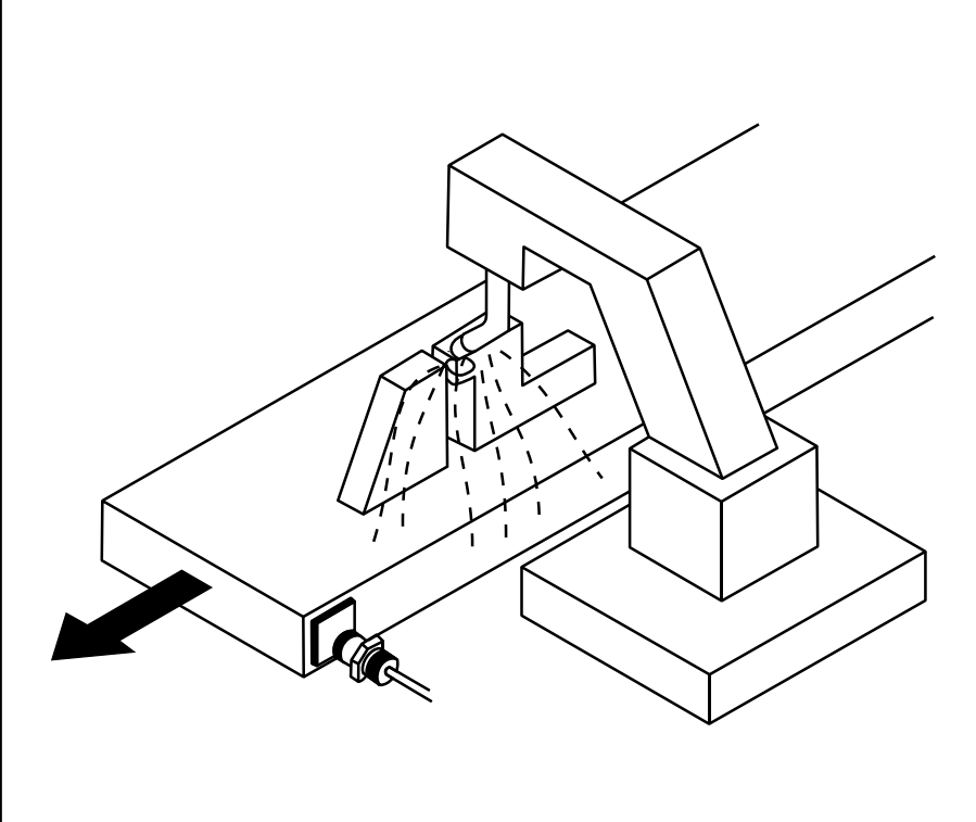
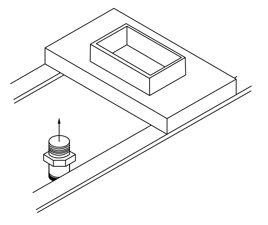
7. Positioning an object on a welding bed
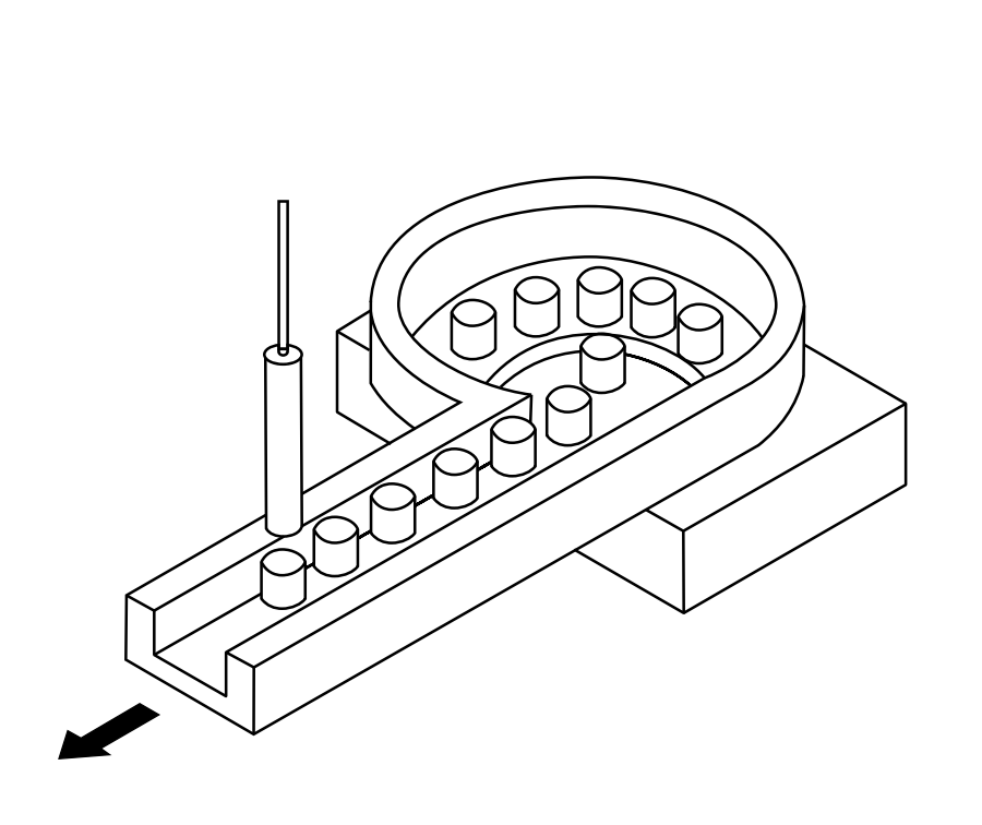
8. Detecting metal parts in a feeder
9. Detecting a moving aluminum template
CATALOG 07
Type and Specification
General proximity-sensor type and specification
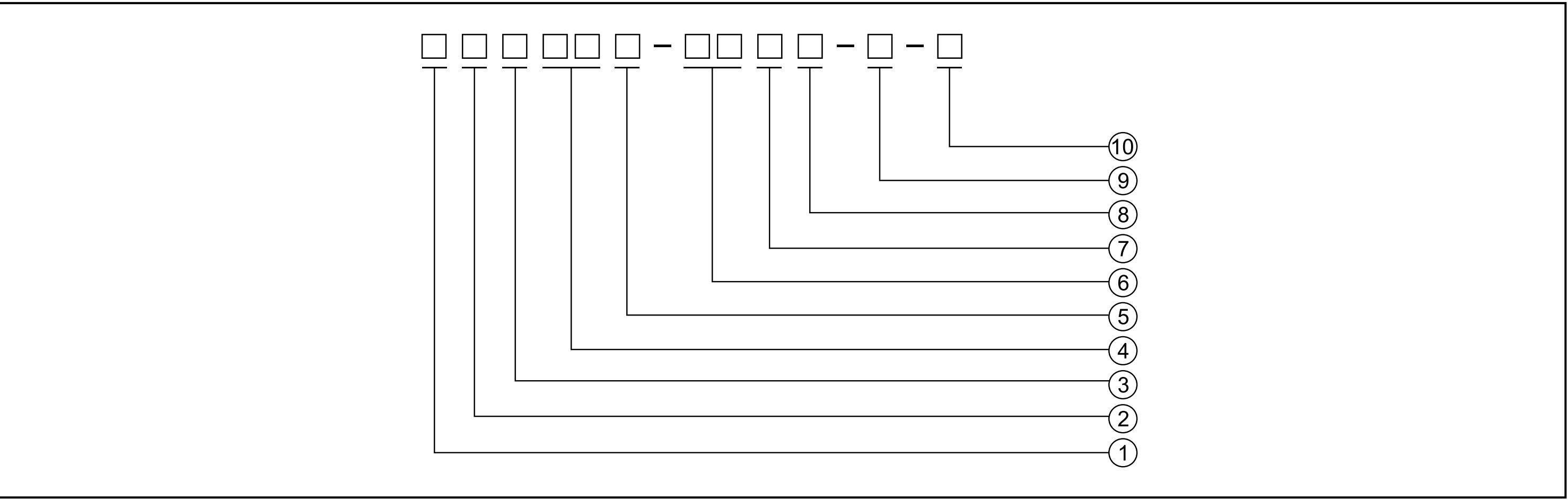
1. Code 2. Type I: Inductive C: Capacitive M: Magnetic 3. Shape □: Metal cylindrical threaded body P: Plastic cylindrical threaded body O: Plastic cylindrical body S: Short cylindrical threaded body N: Square R: Square assembly Q: Flat D: Round peg U: Slot C: Special | 4. Sensing distance 5. Category | 6. Shape size 04: 4 mm 05: 5 mm 06: 6 mm 08: 8 mm 12: 12 mm 18: 18 mm 30: 30 mm 7. Output form 8. Output state 1: NO 2: NC 3: NO + NC 4: Relay contact | 9. Non-standard voltage A: 20–250 V AC B: 90–250 V AC C: 380 V AC D: 10–30 V DC E: 10–60 V DC F: 8.2 V DC G: 5–60 V DC L: 15–30 V DC H: 20–30 V DC I: 10–40 V DC J: 5 V DC S: 20–250 V AC/DC T: 12–24 V DC Temperature codes □: -25 to +120 °C G: +120 to +150 °C D: -40 to +70 °C | 10. Connector □: 2 m cable E1: M8 three-pin connector E2: M12 four-pin connector E3: M8 four-pin connector E4: M12 four-pin stepped connector (catalog wording) E5: M12 five-pin connector |
Photoelectric-sensor type and specification
1. Code 2. Type | 3. Shape 4. Shape size 12: 12 mm 18: 18 mm 30: 30 mm | 5. Detecting distance 10: 10 cm 30: 30 cm 5: 5 m 10: 10 m 6. Detecting type | 7. Output form N: Three-wire DC NPN P: Three-wire DC PNP D: DC A: AC Q: AC + DC 8. Output state | 9. Connector □: With cable E1: M8 three-pin connector E2: M12 four-pin connector E3: M8 four-pin connector E4: M12 four-pin stepped connector (catalog wording) E5: M12 five-pin connector |
The source uses distance code 10 for both 10 cm and 10 m. Confirm the complete model rather than interpreting that code by itself. Category codes, including S, identify the source’s ordering scheme and do not establish certification for a selected model. The brand field in both code schemes is G: GWIEC.
CATALOG 08
Inductive Sensor Families and Characteristic Parameters
Cylindrical type
The source presents this family for corresponding cylindrical applications. Select a replacement using the exact model specifications.
Reverse-polarity and short-circuit protection; direct PLC connection as specified.
For common operating locations, with medium environmental resistance as described in the source.
Red LED operating-state indication.
Economical and simple operation.
Applications include the functions of small switches and limit switches.
IP67 enclosure protection in the source description.
Read the precautions in the operating instructions before use.
Visible type
The source identifies corresponding types from Omron and Autonics; verify the complete model and electrical/mechanical compatibility.
Reverse-polarity and short-circuit protection; direct PLC connection as specified.
Long service life, high reliability and strong environmental resistance.
Reinforced housing.
IP67 enclosure protection in the source description.
Read the operating precautions before use.
All-purpose type
The source identifies corresponding types from Pepperl+Fuchs and TURCK; compatibility requires model-specific confirmation.
Reverse-polarity and short-circuit protection; direct PLC connection as specified.
Current overload protection and imported IC components as described in the source.
Long service life, high reliability and strong environmental resistance.
Red LED operating-state indication.
Full-thread body provides installation adjustment and permits wrench/clamp mounting.
Reinforced housing and cable strain protection.
IP67 enclosure protection in the source description.
Read the operating precautions before use.
Angular, square and slot types
Reverse-polarity and short-circuit protection; direct PLC connection as specified.
Economical and simple operation.
Long service life, high reliability and strong environmental resistance.
Red LED operating-state indication.
IP67 enclosure protection in the source description.
Read the operating precautions before use.
Characteristic parameters
| Item | Catalog description |
| Hysteresis | 10% or more of the detecting distance in the Chinese source; the printed English says 10% below. Confirm the selected model’s value. |
| Detection target | Magnetic metal. Sensing distance decreases for non-magnetic metal. |
| Supply voltage | DC type: 12–24 V DC (6–36 V), with peak-to-peak ripple below 10%. AC type: 110–220 V AC (36–250 V), 50/60 Hz. |
| Current consumption | N/P types: below 13 mA; D type: below 0.8 mA; A type: below 1.7 mA. |
| Control output | N/P types: below 300 mA; D type: below 200 mA; A type: below 400 mA. |
| Circuit protection | N/P/D types: reverse-connection protection, surge absorption and load short-circuit protection. A type: surge absorption. |
| Ambient temperature and humidity | Operation/storage: -30 to +65 °C, without freezing or condensation; relative humidity 35–95%. |
| Insulation resistance | At least 50 MΩ between live parts and the housing, using a 500 V DC megohmmeter. |
| Dielectric withstand | 1000 V AC, 50/60 Hz, 1 minute, between live parts and the housing. |
| Temperature influence | Relative to +23 °C: within ±15% of detecting distance over -30 to +65 °C; within ±10% over -25 to +60 °C. |
| Supply-voltage influence | Within ±10% of detecting distance for a rated-supply variation of ±15%. |
| Enclosure | IP67 (source reference to IEC enclosure classification). |
| Materials | Housing: nickel-plated brass. Sensing face: ABS. |
These are the chapter’s general descriptions. The exact model table and operating instructions determine the applicable voltage, current, temperature, mounting and protection requirements.


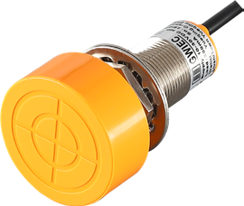 Large-head sensors
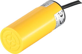 Smooth cylindrical
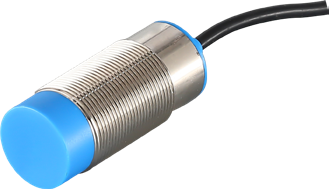 Threaded cylindrical
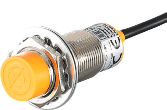 Panel-mount cylindrical
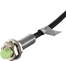 Miniature cylindrical
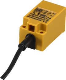 Rectangular sensors