| Availability: | |
|---|---|
| Quantity: | |
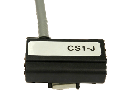
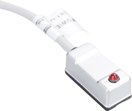
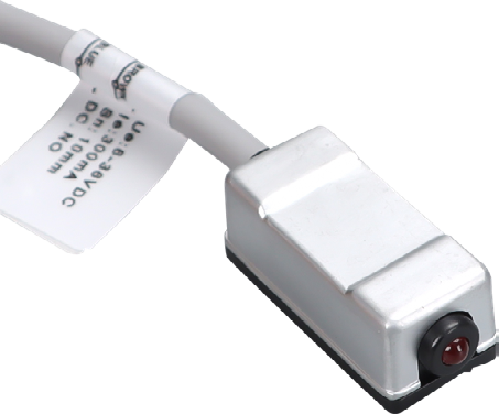
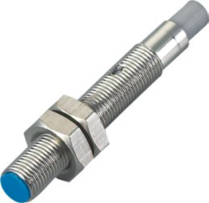
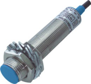
Magnetic cylinder switches / M5 / M8 / M12
GWIEC
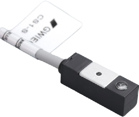
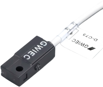
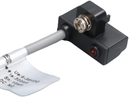
Compare twelve magnetic-switch mechanical forms, including compact cylinder-mount types and M5/M8/M12 threaded bodies. The catalog specifies supply voltage and continuous load current for each form.
| Outward appearance code | 6.5 x 11 x 22.5 mm | 11 x 12 x 28 mm | 11 x 13 x 28 mm | |
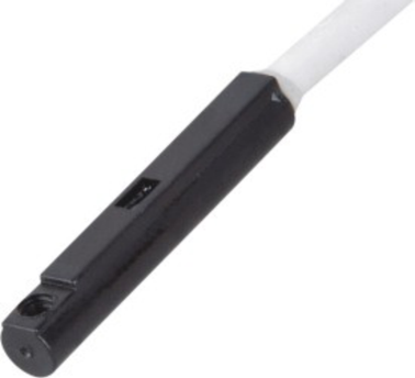
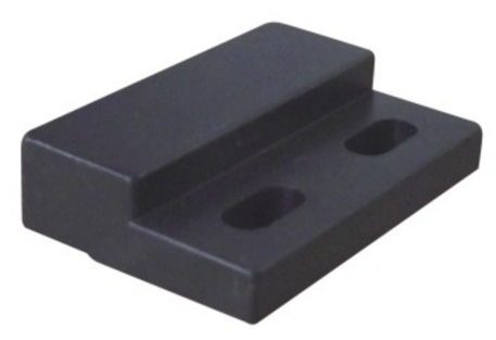
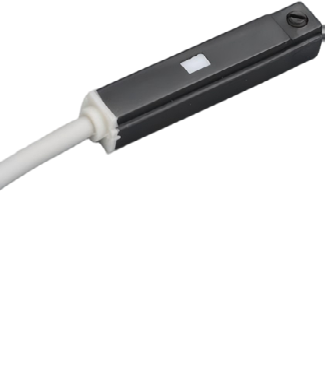
| Product photograph | View original image 6.5 x 11 x 22.5 mm product photograph | View original image 11 x 12 x 28 mm product photograph | View original image 11 x 13 x 28 mm product photograph | |
| Technical parameters | ||||
| Catalog model code | Not separately listed; identify by drawing | Not separately listed; identify by drawing | Not separately listed; identify by drawing | |
| Supply voltage | 5–220 V AC/DC (catalog) | 5–220 V AC/DC (catalog) | 5–220 V AC/DC (catalog) | |
| Continuous load current | 100 mA | 100 mA | 100 mA | |
| Connection | Cable; material and length can be customized | Cable; material and length can be customized | Cable; material and length can be customized | |
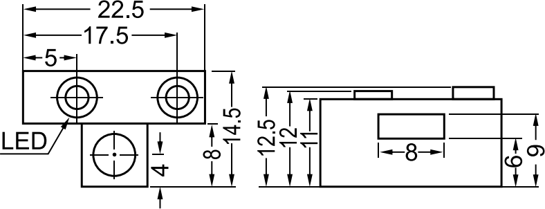
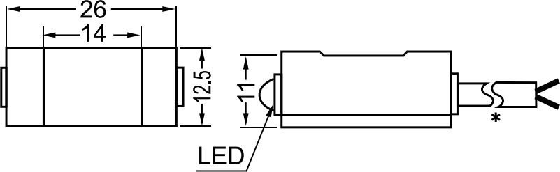
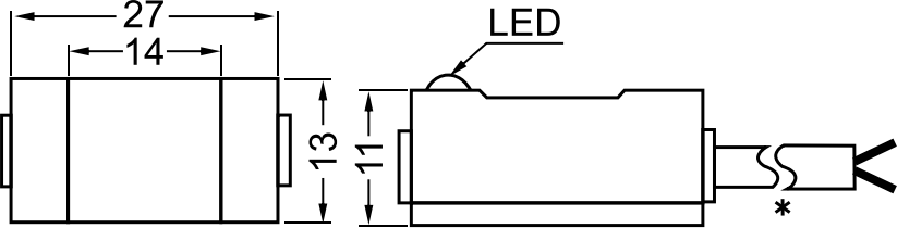
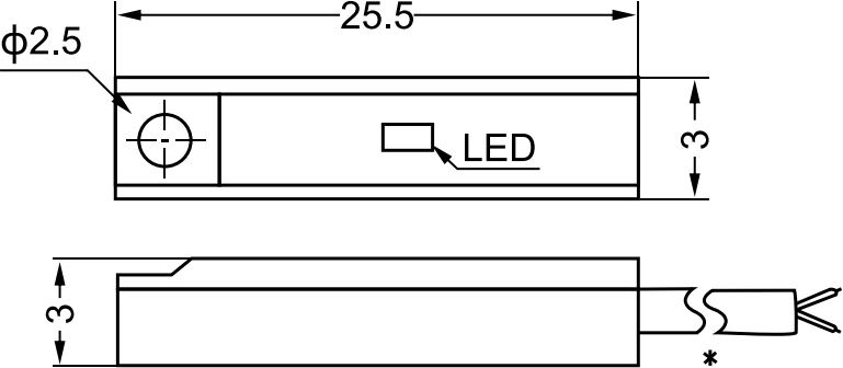
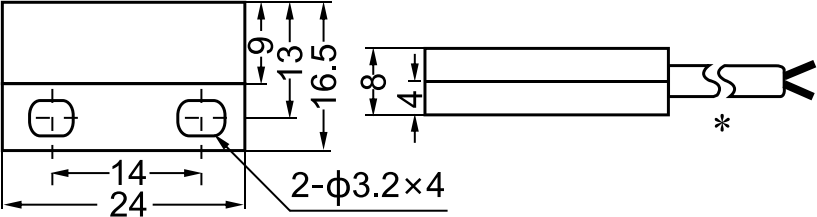
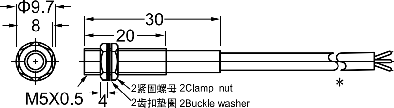
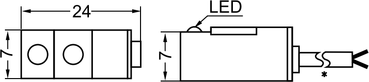
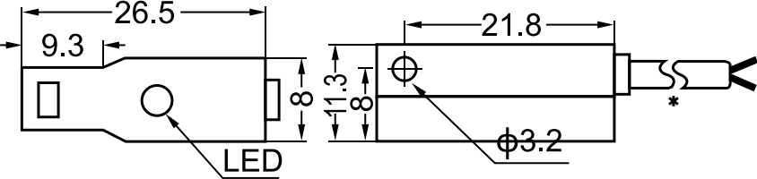
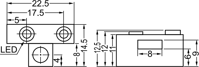
| Dimensions | See original engineering drawing | See original engineering drawing | See original engineering drawing | |
| Engineering drawing Click to enlarge | View original image Magnetic switches — page 29 group 1 engineering drawing | View original image Magnetic switches — page 29 group 1 engineering drawing | View original image Magnetic switches — page 29 group 1 engineering drawing | |
| Outward appearance code | 12 x 36 x 36 mm | 8 x 16.5 x 24 mm | M5 x 1 x 30 | |
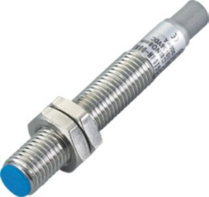
| Product photograph | View original image 12 x 36 x 36 mm product photograph | View original image 8 x 16.5 x 24 mm product photograph | View original image M5 x 1 x 30 product photograph | |
| Technical parameters | ||||
| Catalog model code | Not separately listed; identify by drawing | Not separately listed; identify by drawing | Not separately listed; identify by drawing | |
| Supply voltage | 5–220 V AC/DC (catalog) | 5–220 V AC/DC (catalog) | 5–220 V AC/DC (catalog) | |
| Continuous load current | 100 mA | 100 mA | 100 mA | |
| Connection | Cable; material and length can be customized | Cable; material and length can be customized | Cable; material and length can be customized | |
| Dimensions | See original engineering drawing | See original engineering drawing | See original engineering drawing | |
| Engineering drawing Click to enlarge | View original image Magnetic switches — page 29 group 2 engineering drawing | View original image Magnetic switches — page 29 group 2 engineering drawing | View original image Magnetic switches — page 29 group 2 engineering drawing | |
| Outward appearance code | 15 x 14 x 33.5 mm | 8 x 11 x 26 mm | 6.5 x 11 x 22.5 (adjustable mount) mm | |
| Product photograph | View original image 15 x 14 x 33.5 mm product photograph | View original image 8 x 11 x 26 mm product photograph | View original image 6.5 x 11 x 22.5 (adjustable mount) mm product photograph | |
| Technical parameters | ||||
| Catalog model code | Not separately listed; identify by drawing | Not separately listed; identify by drawing | Not separately listed; identify by drawing | |
| Supply voltage | 5–220 V AC/DC (catalog) | 5–220 V AC/DC (catalog) | 5–220 V AC/DC (catalog) | |
| Continuous load current | 100 mA | 100 mA | 100 mA | |
| Connection | Cable; material and length can be customized | Cable; material and length can be customized | Cable; material and length can be customized | |
| Dimensions | See original engineering drawing | See original engineering drawing | See original engineering drawing | |
| Engineering drawing Click to enlarge | View original image Magnetic switches — page 30 group 1 engineering drawing | View original image Magnetic switches — page 30 group 1 engineering drawing | View original image Magnetic switches — page 30 group 1 engineering drawing | |
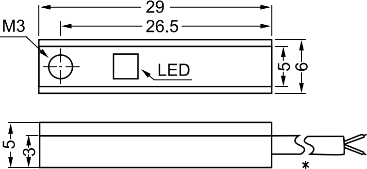
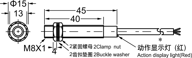
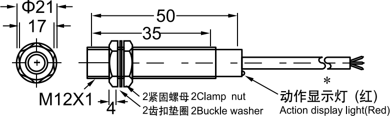
| Outward appearance code | 6 x 5 x 29 mm | M8 x 1 x 30 | M12 x 1 x 50 | |
| Product photograph | View original image 6 x 5 x 29 mm product photograph | View original image M8 x 1 x 30 product photograph | View original image M12 x 1 x 50 product photograph | |
| Technical parameters | ||||
| Catalog model code | Not separately listed; identify by drawing | Not separately listed; identify by drawing | Not separately listed; identify by drawing | |
| Supply voltage | 5–220 V AC/DC (catalog) | 5–220 V AC/DC (catalog) | 5–220 V AC/DC (catalog) | |
| Continuous load current | 100 mA | 50 mA | 200 mA | |
| Connection | Cable; material and length can be customized | Cable; material and length can be customized | Cable; material and length can be customized | |
| Dimensions | See original engineering drawing | See original engineering drawing | See original engineering drawing | |
| Engineering drawing Click to enlarge | View original image Magnetic switches — page 30 group 2 engineering drawing | View original image Magnetic switches — page 30 group 2 engineering drawing | View original image Magnetic switches — page 30 group 2 engineering drawing | |
Selection note: The source does not provide a separate model-code or sensing-distance row for these forms. Do not use a photograph label alone as a complete ordering code; supply the required drawing and mounting dimensions.
Values are transcribed from the GWIEC sensor catalog, pages 29–30. A dash means no model is listed in that source cell. Nominal distance and an operating/set distance are different quantities. Select the complete model, output, supply, connection and mounting dimensions together.
Click any product photograph or engineering drawing to open the original image at full size.
Compare magnetic sensor families · All proximity sensor categories · Contact GWIEC for model confirmation