Treating all electrical contactors as interchangeable components is a costly engineering mistake. Using a standard magnetic contactor for a capacitor bank inevitably leads to contact welding. It triggers premature equipment failure and creates severe safety hazards. Power factor correction panels demand specialized mechanical solutions to handle extreme electrical stress. You cannot simply swap components based on standard full-load amp ratings.
This article provides a technical breakdown of structural differences, load categorizations, and crucial selection criteria. We aim to help electrical engineers and procurement teams specify the exact component required for capacitive loads. You will learn how high-frequency transient surges destroy standard units. We also explore why purpose-built contactors successfully prevent these catastrophic system faults.
Key Takeaways
Load Categorization: Standard contactors are typically rated for resistive or inductive loads (AC-1, AC-3), whereas capacitor contactors are specifically engineered for capacitive switching (AC-6b).
Inrush Current Mitigation: Capacitor contactors utilize auxiliary contacts and damping resistors to manage transient inrush currents that can exceed 100 times the nominal current.
Cost vs. Lifespan: While capacitor contactors carry a higher upfront cost, their modular design (allowing for resistor block replacement) and prevention of catastrophic contact welding ensure a drastically lower long-term equipment expense in power factor correction applications.
1. The Core Engineering Challenge: Transient Surge Currents in Capacitor Banks
Switching a capacitor on is uniquely hostile to electrical infrastructure. You must understand the physics of capacitive switching to grasp the danger. At the exact moment of energization, a discharged capacitor lacks any opposing back-electromotive force. It acts almost completely like a short circuit across the line. This physical reality draws massive transient overcurrents from the grid in fractions of a millisecond.
These hazards multiply depending on your system architecture. Single-step capacitor banks pose a significant but manageable threat. When you energize an isolated single-step bank, it can generate inrush currents up to 30 times its nominal rated current. The grid impedance alone provides the only natural limitation to this surge.
Multi-step automatic banks introduce a far more violent dynamic. These systems switch secondary capacitor steps while parallel capacitors already sit energized on the grid. The already-charged capacitors rapidly dump their stored energy into the incoming uncharged capacitor. This parallel discharge creates massive high-frequency surge currents. Frequencies typically range from 3 to 15 kHz. Peak currents routinely spike to over 100 times the nominal system current.
Standard contactors fail violently under these conditions. They completely lack the physical mechanisms to handle such microsecond-level surges. Standard power contacts slam closed during this massive energy rush. The extreme current density instantly vaporizes the metal surfaces. It causes severe arcing across the air gap. The intense heat permanently welds the molten silver-alloy contacts together. This mechanical seizure causes continuous uncontrolled power delivery, triggering downstream system faults and blown fuses.
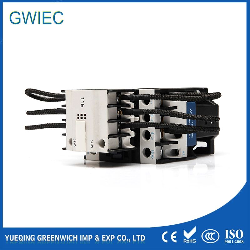
Engineers developed a mechanical solution to solve an inherently electrical problem. The physical anatomy differentiates a capacitor contactor from standard magnetic switches. A standard contactor uses a simple electromagnet to pull all contacts closed simultaneously. In contrast, purpose-built models utilize a complex two-stage mechanical engagement sequence.
The specialized pre-charge circuit mechanism provides the core defense against inrush currents. Manufacturers install an auxiliary contact block on top of or alongside the main contactor housing. These auxiliary blocks feature U-shaped resistive wires. We call them damping resistors. They act as electrical shock absorbers during the initial power surge.
The entire protective process relies on strict mechanical timing. It occurs in mere milliseconds. Here is the step-by-step actuation sequence:
The control coil energizes upon receiving a signal from the power factor controller.
The auxiliary contacts close before the main contacts. They achieve this because their physical travel distance is much shorter.
Current immediately routes through the highly resistive damping wires. This heavily throttles and limits the peak inrush current.
The main power contacts fully close milliseconds later. They provide a clear path of least resistance to carry the continuous load.
The auxiliary contacts mechanically disengage. This critical step prevents the damping resistors from continuously heating and melting under the steady-state load.
This ingenious "millisecond difference" guarantees safe energization. It uses simple mechanical geometry to outsmart violent electrical physics. The main contacts never experience the destructive initial current spike.
We must frame our component evaluation around strict industry standards. The International Electrotechnical Commission (IEC) defines specific utilization categories for electrical switches. These categories dictate exactly what load a switch can legally and safely handle.
Standard contactors fall under categories like AC-1 and AC-3. AC-1 ratings cover non-inductive or slightly inductive loads, such as resistive heating elements. AC-3 ratings apply to squirrel-cage motors that draw moderate starting currents. Neither category accounts for the extreme transient spikes of capacitor banks. You need an AC-6b rated device for these applications. The AC-6b designation proves the switch can safely manage specific capacitive switching transients.
Thermal current endurance marks another crucial dividing line. Standard contactors operate well under normal steady-state thermal requirements. However, capacitor banks constantly absorb voltage harmonics from the grid. This elevates their operating current. IEC 60831-1 standard mandates that capacitors must withstand a continuous thermal current of 1.5 times their nominal rating (1.5 x In). Standard switches melt under this sustained thermal overload. A capacitor contactor features oversized internal busbars and specialized contact alloys to endure this exact 1.5x thermal requirement.
Modularity profoundly impacts long-term maintenance logistics. When a standard contactor fails from arcing, technicians usually scrap the entire unit. The welded contacts render the main body useless. Conversely, AC-6b switches allow for modular repairs. If severe grid events eventually damage the surge suppression wires, you do not throw away the whole switch. You simply unsnap the top auxiliary block and snap on a new one. This modularity heavily cuts ongoing procurement costs.
Below is a summary chart comparing the core operational metrics between standard and capacitive models:
Feature Metric | Standard Contactor | Capacitor Contactor (AC-6b) |
IEC Utilization Category | AC-1 (Resistive) / AC-3 (Motor) | AC-6b (Capacitor Switching) |
Inrush Handling Capability | Under 10x Nominal Current | Up to 100x Nominal Current |
Damping Mechanism | None | Resistive wires via auxiliary block |
Thermal Endurance | Standard Rated Amperage | Continuous 1.5 x In (IEC 60831-1) |
Failure Mode Risk | High risk of welded contacts | Safely managed via pre-charge circuit |
4. Sizing and Selection Criteria for Capacitor Switching
Selecting the right switch requires a shift in traditional sizing mentalities. You must never size an AC-6b switch based purely on standard full-load amps (FLA). Typical FLA sizing works well for motors but leads to dangerous under-sizing for capacitors.
You must size your components based on reactive power. We measure this in kilovolt-amperes reactive (kVAR). Your selection must match the specific kVAR rating of the capacitor bank. Furthermore, you must factor in the precise operating voltage and local ambient temperature inside the panel. A 50 kVAR bank operating at 400V requires a different contactor size than a 50 kVAR bank operating at 480V.
You face tiered solutions based on expected peak currents. Engineers must match the device topology to the system architecture.
Low Peak Environments (<30x Nominal): You can technically use standard contactors here. However, you must heavily derate their sizing. This approach only works for completely isolated, single-step capacitors. We still advise against it for long-term reliability.
Moderate to High Peak Environments (<100x Nominal): You need dedicated capacitor switching models. These units use internal resistive wires. They easily handle standard multi-step power factor correction panels.
Extreme Peak Environments (Unlimited / >100x Nominal): Heavy-duty applications require specialized heavy-duty units. These feature robust, external pre-charge resistor blocks. They protect against extreme harmonic distortions and massive parallel step discharges.
To further clarify sizing parameters, consult the selection table below. It outlines typical kVAR matching thresholds for 400V/415V systems:
Capacitor Bank Rating (kVAR) | Required Thermal Current (1.5x In) | Recommended AC-6b Rating Class |
12.5 kVAR | ~27 Amps | 15 kVAR Contactor |
25 kVAR | ~54 Amps | 30 kVAR Contactor |
50 kVAR | ~108 Amps | 60 kVAR Contactor |
75 kVAR | ~162 Amps | 80 kVAR Contactor |
5. Implementation Risks and Diagnostic Realities
Ignoring specification protocols triggers a severe chain reaction of hardware failures. A welded standard contactor in a capacitor circuit does not quietly destroy itself. It initiates cascading failures throughout your facility. When contacts weld permanently shut, they continuously feed grid harmonics into the capacitor. The capacitor overheats and bulges. Eventually, this over-voltage condition blows panel fuses and trips main breakers. It can even cause severe damage to downstream motors or HVAC compressors.
Facility managers must practice proactive acoustic diagnostics. Listen to your power factor panels. You should only hear a brief, controlled engagement click during operation. This sharp click indicates proper mechanical seating. Conversely, excessive buzzing or loud humming points directly to a failure symptom. Buzzing usually indicates core lamination wear inside the electromagnet. It can also stem from severe dust ingress preventing the armature from seating. Occasionally, mismatched control coil voltages cause this vibration. The capacitive load itself does not cause loud buzzing.
You must strictly observe safety protocols when diagnosing these panels. Capacitors retain lethal high-voltage charges for several minutes even after the switch fully opens. You must never assume a circuit is dead simply because you hear the contacts disengage. Always emphasize standard discharge protocols. Measure the voltage across terminals and wait for internal bleed resistors to drain the stored charge before attempting any inspection or replacement.
Conclusion
Specifying a purpose-built AC-6b switch is not an optional luxury upgrade. It serves as a strict mechanical necessity for managing capacitive transient overcurrents. The specialized auxiliary contacts and damping wires provide the only reliable defense against destructive 100x current surges.
System integrators and facility managers should immediately audit their existing power factor correction panels. Inspect your boards to ensure maintenance teams have not mistakenly installed standard switches as cheap, quick replacements. Finding and replacing these incorrect parts early prevents catastrophic downtime.
Take action today. Consult manufacturer sizing charts from established brands to match your exact panel requirements. Always specify your replacement parts based on precise kVAR ratings and specific step-configurations to guarantee long-term system stability.
FAQ
A: We do not recommend this, especially for multi-step banks. While heavy derating might survive single-step applications temporarily, standard units lack the damping resistors needed to limit inrush spikes. This absence inevitably leads to long-term contact degradation and welding.
A: Buzzing is typically caused by loose iron core laminations, a drop in control coil voltage, or dirt preventing the armature from seating fully. It is a mechanical or control voltage issue, not a symptom caused directly by the capacitive load itself.
A: In industrial environments, repairing pitted or welded contacts poses a severe safety risk. You should never file down main contacts. However, the external damping resistor blocks on modular AC-6b units can often be replaced independently, saving significant costs.


