Selecting the correct trip class for a thermal overload relay requires a delicate balancing act. You must protect essential motors while accommodating the harsh operational reality of startup in-rush currents. Specify a trip class too fast, and operations suffer from chronic nuisance tripping. Specify one too slow, and costly equipment remains vulnerable to catastrophic thermal damage. This guide breaks down the critical engineering criteria to help you specify the right protection. We will explore regional standard discrepancies between NEMA and IEC frameworks. You will also learn technical evaluation methods. These frameworks help you specify the correct overload protection relay for your industrial motor starters.
Key Takeaways
The 600% Baseline: Trip classes (10, 20, 30) dictate the maximum time in seconds a relay will hold before tripping at exactly 600% of the motor's Full Load Amperage (FLA).
Design Standards Matter: North American NEMA motors are typically robust enough for Class 20 protection, whereas IEC motors generally require the stricter response times of Class 10.
Dangerous Workarounds: Artificially raising the FLA dial or relying on the Service Factor (SF) to prevent nuisance trips during high-inertia starts compromises the I⊃2;t thermal damage curve and risks motor failure.
Technology Shifts: Upgrading from traditional bimetallic to solid-state overload relays offers advanced thermal memory tracking, solving the compounding heat risks of hot-state restarts.
The Engineering Baseline of Trip Classes
What exactly defines a trip class? It is never an arbitrary rating. It dictates the maximum allowable time a unit can sustain 600% of its set Full Load Amperage (FLA). The device must break the circuit before exceeding this time limit. We measure this critical threshold strictly in seconds.
You must understand the core business problem. Motors naturally draw massive amperage to overcome resting inertia during startup. A reliable protective device must distinguish between two distinct events. It must identify a normal, temporary start-up spike. It must also recognize a sustained, damaging mechanical overload. If it fails to differentiate, your production line will suffer.
Consider the physics of the trip curve. The Joule heating law dictates the thermal behavior. The formula is $H \propto I^2Rt$. Heat generation directly correlates to the square of the current. When amperage rises above the steady-state FLA, heat generation explodes. It does not scale linearly. Tripping speeds must accelerate exponentially as current increases. This inverse-time curve protects the internal stator windings. It perfectly mirrors the exact thermal damage curve of the motor itself.
The standard protective envelope relies on two primary data points. First, we use the 600% locked-rotor current limit. This point establishes the actual Class rating. Second, we rely on the continuous 115%–125% FLA operational limit. This ensures safe continuous running without premature shutdowns. These two points anchor the entire protective framework.
Class 10 vs. Class 20 vs. Class 30: Application Framework
We classify devices by their specific response speeds. Each tier serves completely different operational demands. You cannot mix them safely. Let us explore the application framework for each rating category.
Class 10 (Fast Response)
This class trips in 10 seconds or less at 600% FLA. It provides highly aggressive thermal protection.
Evaluation Criteria: It remains ideal for highly sensitive equipment. We frequently specify it for hermetically sealed motors. It perfectly protects submersible pumps and environments facing strict forced-cooling constraints.
Risk: It remains highly prone to nuisance tripping. If you apply it to heavy industrial loads, the motor will never reach full speed.
Class 20 (Standard Industrial)
This class trips in 20 seconds or less at 600% FLA. It represents a balanced approach to motor control.
Class 30 (High Inertia/Heavy Duty)
This class trips in 30 seconds or less at 600% FLA. It allows massive motors to accelerate slowly.
Evaluation Criteria: We reserve it exclusively for heavy, long-acceleration applications. Common examples include large centrifugal fans, massive blowers, and industrial rock crushers.
Implementation Reality: Using this class often requires specialized motor designs. A standard unit will melt under this profile. You usually need Mill Duty motors. They can absorb prolonged heat without suffering stator degradation.
Trip Class Comparison Chart
Trip Class | Tripping Time at 600% FLA | Ideal Application Profile | Nuisance Trip Risk (Heavy Load) |
Class 10 | ≤ 10 Seconds | Sensitive, hermetically sealed, submersible | High |
Class 20 | ≤ 20 Seconds | General industrial, standard conveyors | Medium |
Class 30 | ≤ 30 Seconds | High inertia fans, blowers, crushers | Low |
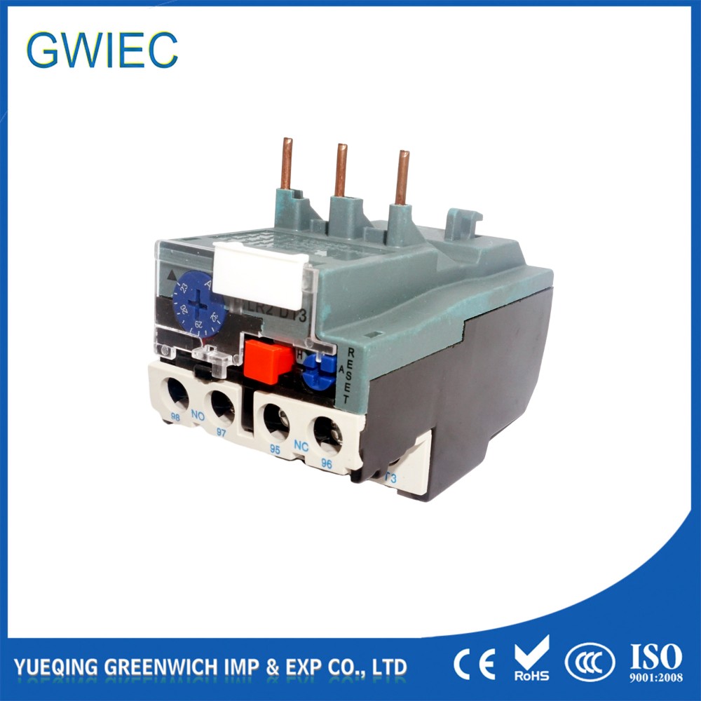
The Impact of NEMA vs. IEC Standards on Specification
A common failure point in procurement happens when integrating global components. Engineers sometimes overlook regional electrical standards. NEMA and IEC design philosophies differ greatly. A sourcing disconnect here causes catastrophic failures down the line.
North American NEMA standards prioritize physical robustness. Manufacturers build these motors with heavy copper windings. They include massive cast-iron frames. This extra material absorbs significant heat. It acts as a massive thermal sponge during rough startups. Because of this extra mass, they easily withstand Class 20 profiles. They tolerate much longer heating cycles. NEMA motors also feature inherent Service Factors. A 1.15 SF is very common. This provides a 15% safety buffer for temporary overloads.
IEC-rated motors follow a completely different design philosophy. European engineering optimizes material usage heavily. Manufacturers engineer them to much tighter tolerances. They use less excess copper and steel. This makes them lighter and more efficient. However, they lack that extra thermal mass. They usually offer a flat 1.0 SF. You have zero buffer for continuous overloads. Because they lack extra mass, they fundamentally rely on Class 10 protection. They heat up rapidly under locked-rotor conditions.
This creates a strict specification rule. Do not apply a Class 20 relay to a standard IEC motor. Many technicians try this to solve annoying start-up issues. It is a terrible mistake. If you do this, you guarantee the motor will burn out. The stator will melt before the relay trips during a genuine locked-rotor event. Always align your protective standard with your motor nameplate.
Troubleshooting Nuisance Trips: Root Causes and Band-Aid Fixes
Nuisance trips frustrate machine operators and maintenance teams. However, bypassing safety mechanisms leads directly to disaster. You must address the root cause appropriately instead of using band-aid fixes.
First, recognize the extreme danger of manipulating FLA settings. A prevalent field error involves dialing up the current protection threshold. Technicians do this to avoid trips on high-inertia start-ups. This completely bypasses the protective envelope. The unit can no longer sense a true overload. The motor will inevitably fail from overheating.
Next, you must carefully evaluate thermal memory decay. Previous running cycles heavily impact tripping speed.
Cold Start: The motor starts at ambient temperature. It utilizes its full thermal capacity. It can handle a normal start cycle.
Hot Start: A motor that just ran possesses a high internal temperature. Its thermal capacity remains depleted.
A hot-state restart will trip significantly faster than the stated Class rating. The internal protective mechanism remembers the previous heat. It trips early to save the windings.
Phase unbalance also triggers early shutdowns frequently. Unbalanced voltage phases cause disproportionate heating in the stator. Modern relays detect this dangerous condition. They intentionally bias the trip point lower. They trip prematurely to save the motor. Remember, this is a protective feature. It is never a defect.
Best Practices: NEC Compliant Workarounds
Some industrial processes involve extreme high-inertia loads. Large industrial centrifuges are a great example. These machines take a long time to reach full speed. Even a Class 30 setting trips prematurely here. What do you do? Follow these NEC-compliant steps:
Consult NEC Article 430 guidelines for heavy industrial motor loads.
Implement an approved start-up bypass or electrical shunt.
Wire the circuit to bypass the protective unit during initial acceleration.
Use a timer relay to re-engage the protection only after steady-state RPM is reached.
This strategy keeps your control panel fully compliant. It protects equipment during standard operation while allowing massive loads to start.
When specifying a protective unit, you must choose the right internal technology. The market offers two primary categories. Each brings different capabilities to your panel.
These units rely on basic mechanical metal expansion. Two distinct metals heat up together. They bend at different rates to physically break the circuit. They represent a highly cost-effective solution. They dominate budget-conscious procurement lists.
However, they require ambient temperature compensation features. Without this feature, a hot summer day causes false trips. A freezing factory floor prevents them from tripping in time. They offer decent reliability for simple tasks. They remain heavily limited in absolute precision.
Solid-State / Electronic Relays (Modern Best Practice)
Solid-state models use a modern heaterless design. They use current transformers internally. They measure amperage directly using electronics. They do not rely on clumsy heat transfer mechanisms.
This design provides exceptional scalability and accuracy. They remain highly immune to ambient temperature shifts. A hot room does not affect their math. Many models feature switchable trip classes. You can turn a small dial on the front face. You can select Class 10, 15, 20, or 30 on a single unit. This drastically reduces your spare parts inventory.
They also offer advanced digital protection. You gain superior phase loss detection. They spot a dropped phase instantly. You also get highly accurate digital thermal memory tracking. The internal microprocessor tracks heat mathematically. It flawlessly manages hot and cold state start-ups.
We highly recommend solid-state options for high-stakes manufacturing lines. The slight upfront cost premium pays for itself rapidly. You easily offset the initial expense. You reduce expensive motor replacements. You also minimize frustrating diagnostic downtime on the factory floor.
Conclusion
Selecting a trip class requires strict calculation, not personal preference. You must carefully weigh motor thermal mass against your specific load inertia. Bypassing safety limits only destroys expensive hardware.
Procurement and engineering teams should take immediate action. First, audit your facility motor nameplates today. Note the specific NEMA or IEC ratings. Document their Service Factors. Second, standardize your facility on Class 10 or Class 20 units based strictly on this audit data. Do not mix and match blindly. Finally, evaluate solid-state electronic options for applications suffering from chronic hot-start tripping. You will improve your operational uptime. You will safeguard your most valuable capital equipment.
FAQ
Q: Can I adjust the Service Factor (SF) to solve nuisance tripping?
A: No. The Service Factor is designed to handle temporary voltage anomalies or momentary overload shocks. It is not designed for continuous heavy running or extended start-ups. Running your motor consistently at the SF limit drastically shortens its lifespan and causes insulation failure.
Q: What is a Class 5 overload relay used for?
A: Class 5 trips extremely fast, taking under 5 seconds at 600% FLA. Engineers specify it for fractional horsepower motors. It protects highly delicate, friction-sensitive equipment. It suits any application where a slight delay causes immediate physical machine damage.
Q: Why does my motor trip faster on a hot restart?
A: Units possess "thermal memory." A recently run motor has a high internal temperature. Its cooling cycle is incomplete. The relay accounts for this severely reduced thermal capacity. It triggers much earlier than the baseline Class rating to prevent compounding heat from melting the stator.


