Unexpected power factor correction (PFC) bank failures inflict heavy operational costs on industrial facilities. You routinely face regulatory penalties for poor power factor. You risk localized thermal events. You might even experience complete line downtime when critical components fail. Switching capacitive loads presents unique, punishing challenges to electrical infrastructure. Standard contactors applied to PFC systems frequently experience catastrophic premature failures. They simply cannot handle the extreme electrical forces unleashed during energization. This article gives facility engineers and procurement teams a precise diagnostic framework. You will learn how to identify the exact root causes of these failures rapidly. We provide an evidence-based matrix to help you specify the correct replacement capacitor contactor. By understanding the underlying physics, you can prevent recurring damage and secure long-term system reliability.
Key Takeaways
Standard electromechanical contactors fail in PFC systems due to zero-impedance inrush currents (up to 150x nominal) and high transient recovery voltage (TRV).
The four most common failure modes are contact welding, restrike damage, pre-insertion resistor (PIR) burnout, and mechanical linkage degradation.
Introducing detuning reactors mitigates inrush but permanently alters the steady-state thermal requirements of the contactor.
Selecting a replacement power factor correction contactor requires balancing switching frequency, load architecture (individual vs. banked), and harmonic distortion (THDv) limits.
Understanding contactor mortality requires looking at the physical realities of capacitive switching. A fully discharged capacitor acts as a near-zero impedance short circuit upon energization. This creates a severe inrush current anomaly. Individual PFC units might see an inrush peak at 30 times the nominal current. However, banked or group PFC systems present a far more hostile environment. In these architectures, adjacent charged capacitors discharge directly into the newly connected step. They bypass the impedance of the main power transformer. You can routinely see peaks exceeding 150 times the nominal current. These transients oscillate at extremely high frequencies, typically between 2 and 15 kHz.
De-energization introduces an equally destructive phenomenon. You must manage transient recovery voltage (TRV). When you interrupt a capacitive load, the physics work against you. Because current leads voltage by exactly 90 degrees, interrupting the current at the zero-crossing leaves the capacitor fully charged at peak system voltage. A massive voltage differential immediately develops across the opening contacts of the contactor. This differential often exceeds 2.0 p.u. (per unit) of the system voltage.
This strict combination guarantees failure for standard hardware. You face intense thermal stress on closure. You face extreme dielectric stress on opening. These conditions strictly prohibit the use of standard AC-3 duty contactors. Without specialized mitigation, standard units will rapidly destroy themselves.
Identifying the exact failure mechanism helps you implement the correct corrective action. System operators typically encounter four primary failure modes. We will examine the underlying mechanisms and their corresponding operational symptoms.
Contact Welding (Make-Failure)
Extreme inrush current melts the contact material before the mechanism achieves full closure pressure. The localized Joule heating turns the contact faces into liquid metal. They fuse together instantly. As a symptom, the contactor remains mechanically stuck in the closed position. It permanently connects the capacitor step to the grid. You will likely observe system over-correction or severe harmonic resonance.
Restrike Damage (Break-Failure)
When opening the circuit, the dielectric medium between the separating contacts must recover its insulating properties quickly. If it cannot withstand the rapid TRV rise, the arc re-ignites across the gap. We call this a restrike. Symptoms include high-frequency voltage transients on the network. You will also find heavily carbonized contact surfaces and accelerated erosion of the arc chutes.
Pre-Insertion Resistor (PIR) Burnout
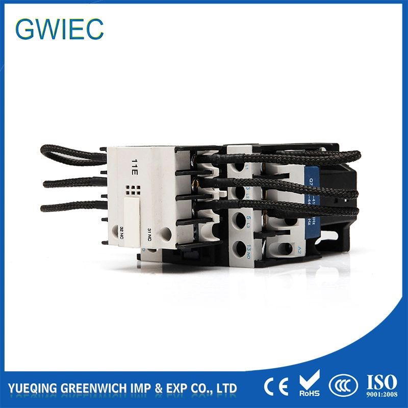
Specialized contactors use early-make auxiliary contacts paired with wire-wound resistors. These resistors dampen the deadly inrush peak. However, they have strict thermal limits. If your switching frequency exceeds the thermal dissipation limit of the resistors, they overheat. You will notice charred resistor blocks. You might find open-circuit auxiliary paths. Shortly after this, the main contacts will suffer catastrophic welding because they now take the full inrush.
Mechanical Operating Mechanism Degradation
The violent electromagnetic forces generated by repetitive, high-frequency inrush currents physically stress the internal components. The armature, return springs, and plastic linkages endure massive shockwaves. Over time, you will notice sluggish operation. The unit might suffer incomplete closure, leading to single-phasing. A loud, persistent AC hum from the coil often precedes total mechanical lockup.
Accurate field diagnostics prevent you from replacing parts blindly. You must overcome standard measurement blind spots. Standard multimeters and basic power quality analyzers often miss microsecond-level transients entirely. They lack the necessary sampling rates. Accurate diagnosis of inrush peaks and TRV requires an oscilloscope. You must pair it with a high-bandwidth current probe. Avoid using standard Rogowski coils for these measurements. They struggle to capture MHz-level transient oscillations accurately.
Perform a strict visual and mechanical inspection on every failed unit. Use the following checklist to standardize your approach:
Verify the current operation counters against the manufacturer's specified electrical lifespan.
Inspect the PIR blocks for early signs of discoloration or thermal warping.
Measure pole-to-pole contact resistance using micro-ohm testing equipment. This detects early-stage erosion long before catastrophic welding occurs.
Check the physical alignment of the auxiliary contact bridges.
You must also perform a system-level harmonic evaluation. Check if the contactor failures correlate with the recent installation of Variable Frequency Drives (VFDs). VFDs introduce significant non-linear loads. High Voltage Total Harmonic Distortion (THDv) acts as an invisible amplifier for dielectric stress. When THDv exceeds the IEEE 519 limits of 8%, the thermal and dielectric burdens on your contactor multiply exponentially.
Engineers frequently add series detuning reactors (chokes) to fix harmonic resonance issues. While effective for the network, this modification drastically changes the contactor requirements. You face a major shift in operational stress.
Reactors successfully limit inrush severity. They introduce vital impedance. This often allows standard contactors to survive the initial make-operation without welding. However, detuning reactors inevitably increase the steady-state current multiplier. The voltage across the capacitor rises, which in turn draws a higher continuous current through the contactor.
Consider the sizing realities outlined in the chart below. As the detuning percentage increases to block lower-order harmonics, the continuous current penalty grows.
| | Harmonic Detuning Reactor Impact Chart |
Detuning Rate (%) | Target Harmonic Mitigated | Continuous Current Multiplier |
5.67% | 5th Harmonic | Approx. 1.03x to 1.04x |
7.00% | 5th Harmonic (Aggressive) | Approx. 1.04x to 1.05x |
14.00% | 3rd Harmonic | Approx. 1.08x to 1.10x |
Industry standards dictate strict de-rating requirements based on these altered thermal profiles. If you utilize standard electromechanical contactors in a choked PFC system, you must de-rate them heavily. You must size the contactor to handle at least 1.5 times the nominal capacitor current. Failing to apply this de-rating rule guarantees thermal overload. Ensure your selected power factor correction contactor accounts for this continuous current penalty to prevent coil burnout.
Upgrading a damaged unit requires matching the hardware to your specific grid topology. You generally evaluate three distinct solution categories. Each carries specific advantages and limitations.
These units utilize built-in pre-charging resistors. They delay the main contact closure by a few milliseconds. The resistors absorb the destructive inrush peak. They offer the best fit for unchoked, multi-step banked PFC systems experiencing low-to-medium switching frequencies. However, they possess a significant drawback. They remain highly vulnerable to rapid-cycling thermal overload if the PFC controller commands too many operations per hour.
Vacuum technology alters the arc-quenching physics completely. The contacts operate inside a sealed vacuum bottle. This provides exceptional dielectric recovery rates. A vacuum gaps recovers at greater than 20 kV/μs. Air only manages 0.1 to 0.5 kV/μs. This effectively eliminates restrike damage. They represent the best fit for heavy industrial environments, high-switching-frequency applications, and large KVAR banks. Their primary drawback involves a higher initial capital expenditure. However, their superior electrical endurance offsets early replacement needs.
You can use over-sized standard contactors exclusively in heavily choked or detuned circuits. In these setups, permanent current-limiting reactors mathematically control the inrush. They offer the best fit for systems where large reactors already exist. You must rigorously apply the 1.5x continuous current de-rating factor.
| | Replacement Matrix for PFC Contactors |
Contactor Type | Best Application Profile | Primary Limitation |
Capacitor-Duty (PIR) | Unchoked banks, low switching frequency | Resistor burnout under rapid cycling |
Vacuum Contactor | High switching frequency, large KVAR loads | Higher initial capital requirement |
De-rated Standard | Heavily choked systems only | Requires massive physical footprint |
You must verify strict compliance parameters before purchasing. Ensure any specified capacitor contactor,power factor correction contactor formally complies with the IEC 62271-106 standard for capacitive switching. Evaluate the expected switching cycles per day. Compare this daily operational burden against the contactor’s maximum electrical endurance rating to guarantee long-term stability.
Conclusion
Upgrading or replacing a failed contactor in a PFC bank is never a simple one-to-one swap. You must match the contactor’s arc-quenching and inrush-handling capabilities directly to the specific architecture of your capacitor bank. Overlooking system variables like detuning reactors or adjacent charged capacitors leads directly to repeat failures.
As an immediate next step, we strongly recommend conducting a baseline power quality audit. Measure your facility's actual THDv and capture true microsecond inrush peaks. Once you secure this hard data, you can finalize the specification for a highly specialized capacitor-duty or vacuum contactor with complete confidence.
FAQ
A: No. Standard AC-3 contactors lack the necessary mechanisms to handle capacitive loads safely. You face an immediate risk of contact welding due to massive, unmitigated inrush currents. The only exception occurs if your circuit features substantial series inductance or detuning chokes that strictly limit this inrush to manageable levels.
A: Your PFC system likely exceeds the manufacturer's maximum allowed switching operations per hour. Rapid cycling prevents adequate cooling. The resistors absorb massive energy during each closure. Without sufficient thermal recovery time, the blocks overheat, char, and eventually fail entirely.
A: A capacitor contactor utilizes specialized early-make auxiliary contacts paired with damping resistors. These elements pre-charge the capacitor to restrict initial inrush currents safely. Furthermore, they incorporate anti-weld silver-alloy contact materials designed explicitly to survive the violent electrical stresses unique to capacitive switching operations.


