Electrical panel design relies heavily on precise component selection to ensure safety and efficiency. Unfortunately, engineers often choose the wrong protection hardware for their specific applications. Selecting an incorrect protection device leads to two highly expensive outcomes in industrial environments. You either experience frustrating nuisance tripping during normal motor startup sequences. Or, you face catastrophic equipment failure due to completely unmitigated thermal stress.
Resolving this dilemma requires a deep understanding of component capabilities. We will clarify the physical and functional distinctions between thermal relays and circuit breakers. You will discover exactly when to deploy each specific device for optimal system safety. Furthermore, we will demystify when an integrated solution becomes structurally appropriate. By understanding these principles, you can protect both your wiring infrastructure and your expensive rotating equipment.
Key Takeaways
Circuit breakers are primarily sized to protect the circuit's wiring from sudden high-current events (short circuits and major surges).
A thermal overload relay is sized based on the motor's Full Load Amperage (FLA) to protect the end device from gradual overheating and phase failures.
Circuit breakers independently sever power; thermal relays cannot break high voltage directly and must be wired in series with a contactor.
Advanced topologies involving Variable Frequency Drives (VFDs) dictate specific integration rules to prevent drive damage during fault conditions.
The Core Difference: Protecting the "Wire" vs. Protecting the "Device"
Engineers must first understand the differing mandates of circuit breakers and thermal relays. They do not perform the same job. They monitor different fault conditions within the same electrical system. Blurring the lines between them creates severe safety vulnerabilities.
The Circuit Breaker's Mandate (Wire Protection)
A circuit breaker functions as the primary line of defense for the overall circuit. We install these devices to prevent catastrophic electrical fires. You size a breaker according to the ampacity of the conductors. If the copper wire can safely carry 50 amps, the breaker must trip before current exceeds this limit. It strictly protects the cable infrastructure.
Breakers respond aggressively to overarching system faults. They excel at clearing massive short circuits in milliseconds. However, they lack the sensitivity to detect minor, prolonged motor overloads. A motor drawing 115% of its rated current will eventually melt its internal windings. A standard breaker will completely ignore this 15% overload because the wire itself remains perfectly safe.
The Thermal Relay's Mandate (Device Protection)
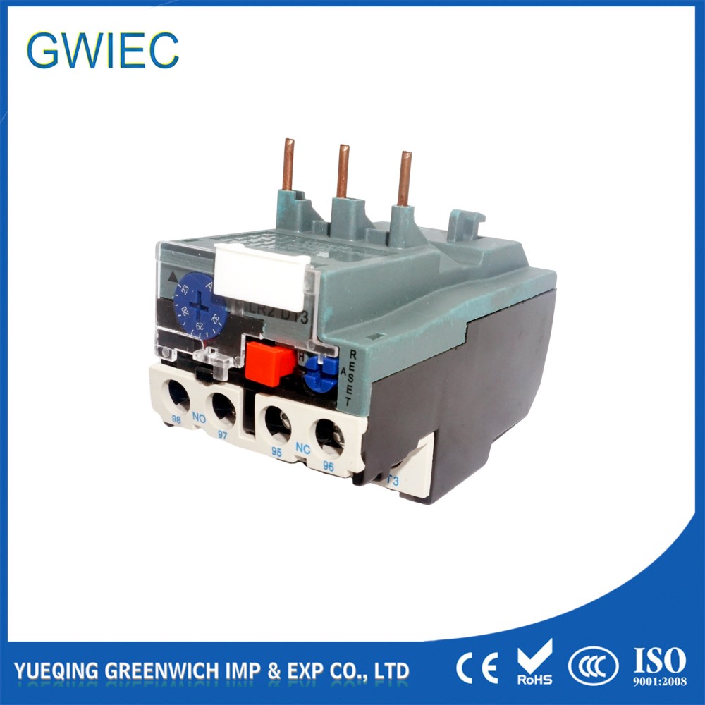
Unlike a breaker, a thermal overload relay functions exclusively as a dedicated equipment guardian. We typically use them to protect industrial motors. The device utilizes a sensitive bimetallic strip mechanism. This strip curves predictably under sustained heat. It physically reacts to the accumulated thermal effect of excess current.
This mechanism operates with a much higher tolerance for temporary spikes. Motors draw massive inrush current when they first spin up. This startup spike can easily reach 600% of the normal operating current. The bimetallic strip absorbs this brief heat without bending far enough to trip. It specifically ignores normal inrush current while remaining vigilant against long-term thermal buildup.
Mandate Comparison Chart
Feature | Circuit Breaker | Thermal Overload Relay |
Primary Target | Circuit wiring (Conductors) | End equipment (Motors) |
Sizing Metric | Cable Ampacity | Motor Full Load Amperage (FLA) |
Short Circuit Response | Instantaneous disconnection | None (Relies on upstream breaker) |
Overload Sensitivity | Low (Ignores minor overloads) | High (Detects gradual heat buildup) |
Tripping Mechanics and Industry Standards (Evaluating the Evidence)
Understanding how these components disconnect power requires looking at their trip curves. The physical science behind their mechanisms dictates their application. You must evaluate the evidence provided by manufacturer data sheets.
Instantaneous vs. Inverse-Time Curves
Breakers rely on magnetic or fast-thermal tripping mechanisms. When a short circuit occurs, the magnetic coil generates massive force immediately. This provides near-instantaneous disconnection during shorts. The breaker forcefully separates the contacts to extinguish the resulting electrical arc. It acts like a digital switch during a crisis.
Conversely, thermal relays utilize a strict inverse-time curve. The logic is simple: the higher the overload current, the faster it trips. However, it purposefully delays action. If a motor jams slightly, current rises. The relay begins to heat up. It waits a predetermined amount of time before interrupting the control circuit. This intentional delay accommodates standard operational spikes without causing frustrating downtime.
Understanding Trip Classes (Class 5, 10, 20, 30)
The industry categorizes this inverse-time delay using specific Trip Classes. These classes define standard evaluation criteria for motor protection. The metric defines how long a device can sustain 720% of its normal load before tripping. Engineers use these classes to match the relay to the physical inertia of the motor load.
Class 5: This class mandates a highly fast trip. The relay must act within 5 seconds at 720% load. We require Class 5 for highly sensitive equipment like submersible pumps. These motors lack external cooling fans and will burn up rapidly if stalled.
Class 10: This represents the industry standard for general-purpose motors. It permits up to 10 seconds of inrush current. You will find Class 10 devices on most standard compressors and basic conveyors.
Class 20 and 30: These classes feature a heavily delayed trip. They tolerate 20 to 30 seconds of massive startup current. Engineers engineer them specifically for high-inertia loads. Massive industrial fans, large centrifuges, and heavily loaded crushers require long spin-up times. A standard Class 10 relay would falsely trip every time you started these heavy machines.
Selecting the wrong trip class guarantees operational failure. Upgrading to a Class 30 device on a standard motor eliminates nuisance tripping, but it destroys the motor during a real stall. Always match the class to the mechanical reality of the load.
System Architecture: Standalone Components vs. Integrated Solutions
Modern electrical panels offer different architectural approaches to motor control. You can build a system using standalone components. Alternatively, you can purchase integrated units that consolidate these functions. Each approach carries distinct advantages and mechanical limitations.
The Traditional Starter Assembly
The traditional approach divides responsibilities across three discrete parts. First, you install a breaker for line protection. Next, you wire a contactor for routine electrical switching. Finally, you attach a thermal relay to the contactor for motor protection. The contactor coil routes through the relay's auxiliary contacts.
This modular approach offers immense flexibility. It is highly advantageous for maintenance budgets. If a power surge destroys the contactor, you only replace the contactor. If the thermal element fails, it is cheap and easy to replace the individual component. You retain maximum control over the specific brand and rating of each part.
However, this setup carries a significant physical limitation. It consumes a massive amount of panel space. Mounting three separate devices for a single motor eats up valuable DIN rail real estate. Wiring them together requires extra labor and creates more potential points of connection failure.
Motor Protection Circuit Breakers (MPCBs)
Manufacturers developed Motor Protection Circuit Breakers (MPCBs) to solve the space problem. An MPCB represents a highly integrated engineering solution. It combines short-circuit protection, a manual disconnect switch, and overload protection within a single housing.
The primary advantage is spatial efficiency. Using an MPCB saves substantial DIN rail space. It dramatically simplifies your panel's internal wiring logic. You run power through one device instead of three. This reduces labor costs during the initial panel build. It also provides a clean, modern aesthetic inside the enclosure.
Despite these benefits, MPCBs present distinct limitations. They carry a higher upfront procurement cost. More importantly, they lack the granular, highly customized trip curves available in standalone devices. If you need a strict Class 30 delay for a heavy fan, a standard MPCB might not accommodate it. Furthermore, they often demonstrate a slower response to massive electrical surges compared to dedicated, standalone fuses.
Implementation Risks & Real-World Operating Scenarios
Theoretical knowledge must translate into practical panel building. Engineers face severe implementation risks when applying these devices in complex environments. Failing to anticipate real-world operating scenarios leads to expensive hardware destruction.
The VFD "One-to-Many" Trap
Variable Frequency Drives (VFDs) introduce unique protection challenges. An implementation reality often trips up novice designers. When running multiple motors off a single VFD, engineers often make a critical mistake. They mistakenly install standard breakers or Motor Circuit Protectors (MCPs) on the drive's output side.
This creates a massive risk for the entire system. If a breaker physically opens the circuit while the VFD is operating under load, it breaks the current path instantly. The internal inductance of the motor abruptly pushes back. This resulting voltage spike travels backward into the VFD. The spike can easily destroy the VFD's internal Insulated-Gate Bipolar Transistors (IGBTs). Replacing a blown VFD costs thousands of dollars.
The solution requires older, proven technology. You must install a traditional thermal relay for each motor on the output side. Do not wire it to break the power lines. Instead, route the relay's normally closed (NC) auxiliary contact back to the VFD’s digital input terminal. When an overload occurs, the relay signals the VFD directly. The drive then safely executes an "external fault" routine. It ramps down the power gracefully without hard-breaking the active electrical lines.
Environmental Sensitivity & Phase Loss
Industrial environments punish electrical components. Standard bimetallic strips can be heavily influenced by ambient panel temperature. If you place a panel in a hot boiler room, the ambient heat pre-warps the strip. This causes premature nuisance tripping. In extreme environments, you must specify ambient-compensated models. These specialized units use a secondary bimetallic strip to cancel out the effects of surrounding air temperature.
Phase loss represents another severe industrial hazard. If one leg of a three-phase system drops out, the motor continues to run on two phases. It pulls massively disproportionate current to compensate. This rapidly melts the motor windings. Modern thermal devices feature built-in phase failure protection. They utilize differential slider mechanisms. If the current across the three poles becomes severely unbalanced, the mechanism forces a trip. This shuts down the contactor immediately, preventing rapid motor burnout.
Procurement Sizing Checklist: Shortlisting the Right Device
Selecting the right protection topology requires a systematic approach. Do not guess when sizing these safety-critical components. Follow this strict procurement checklist to shortlist the exact device your system requires.
Assess the Load Type: You must first define what you are powering. Is this a basic resistive load like a commercial heater? If so, a standard circuit breaker only may suffice. Resistive loads do not generate massive inrush currents. Is it an inductive motor load? Inductive loads mandate thermal relay protection to manage startup surges and gradual heating.
Identify Motor FLA vs. Cable Ampacity: You must read the motor's nameplate data carefully. Locate the Full Load Amperage (FLA) rating. Ensure your selected relay is adjustable. You must map its dial precisely to the motor's exact FLA. Simultaneously, review the upstream breaker. Ensure the breaker maps exclusively to the wire gauge ampacity defined by local electrical codes.
Calculate Space and Budget Constraints: Evaluate your physical enclosure. Measure the available DIN rail space. Compare the upfront cost of a Type-E integrated MPCB against a traditional contactor and relay configuration. If space is tight, the MPCB premium is justified. If panel space is abundant, the modular approach often wins.
Determine Reset Protocol Requirements: Assess your operational environment. Evaluate if the system requires manual resets. Manual resets force an operator to physically inspect the machine after a fault occurs. This promotes safety. Conversely, evaluate if you need automatic resets. Remote pumping stations or inaccessible installations often require automatic resets to restore temporary faults without truck rolls.
Conclusion
Circuit breakers and thermal overload relays are entirely distinct components. They are never interchangeable in motor control applications. They act as complementary devices addressing different ends of the fault spectrum. Breakers watch the wire and react to violent shorts. Relays watch the motor and react to slow, destructive heat.
Your immediate next step is to audit your current motor control panels. Check the dials on your thermal devices to ensure they match the connected motor's FLA precisely. Verify that your chosen Trip Classes align with the mechanical inertia of your loads. Always ensure your selections comply with relevant NEC or IEC electrical codes. Finally, consult with a certified panel builder if you plan on transitioning legacy modular systems to integrated MPCB solutions.
FAQ
Q: Can a circuit breaker replace a thermal overload relay?
A: No. A standard breaker cannot effectively differentiate between a motor's normal startup inrush current and a dangerous, slow-building thermal overload. Breakers protect the wiring infrastructure from shorts. They will either cause nuisance tripping on startup or allow a motor to slowly melt under a mild overload.
Q: Does a thermal relay protect against short circuits?
A: No. Thermal relays react to gradual heat buildup through a bimetallic strip. They lack the physical mechanism to sever massive fault currents. They rely entirely on upstream devices, like breakers or fast-acting fuses, to safely clear high-amperage short circuits.
Q: Why does my thermal overload relay keep tripping on startup?
A: It is likely incorrectly sized for the motor's FLA. Alternatively, the Trip Class setting is inappropriate for your specific application. A Class 10 device acts too fast for a high-inertia load like a massive fan. Heavy loads generally require a Class 20 or 30 rating to prevent false startup trips.


