A tripped thermal overload relay indicates a potential threat to your motor's integrity. Rushing to reset the device without proper diagnosis risks catastrophic motor failure. It also exposes maintenance personnel to severe electrical hazards. Unplanned downtime is undeniably costly for any industrial operation.
However, overriding essential safety controls to force a quick restart compounds financial and operational risks tenfold. You cannot simply press a button and hope for the best. Treating a protection trip as a nuisance ignores the underlying mechanical or electrical stress actively threatening your equipment.
This article provides an evidence-based, safety-first framework for your maintenance teams. You will learn how to accurately diagnose, reset, and test a thermal overload relay. We also outline clear evaluation criteria so you know exactly when to replace or upgrade your existing unit to modern standards.
Key Takeaways
Mandatory Cooling: Bimetallic relays operate on a thermal time constant; resetting requires a strict 5–10 minute physical cooling period to match motor cooling.
Diagnostic Hierarchy: A tripped relay is a symptom, not the root cause. Wiring shorts, mechanical binding, and phase loss must be ruled out prior to resetting.
Testing Integrity: Standard testing requires a digital multimeter to verify the continuity state switch between NC (95/96) and NO (97/98) terminals.
Upgrade Triggers: Frequent false trips or the need for precision monitoring often justify transitioning from traditional thermal to solid-state electronic relays.
Before You Reset: Diagnosing Why the Motor Overload Relay Tripped
Treating a trip as a minor inconvenience rather than a protective intervention is a dangerous habit. This mindset leads directly to repeated component failures and eventual motor burnout. A tripped motor overload relay acts as a symptom of a larger system problem. You must identify the root cause before attempting any restart procedure.
To understand why a trip occurs, we must look at the I⊃2;t principle. Engineers often call this the inverse time curve. The relay easily tolerates brief, high-amperage startup surges. Industrial motors naturally draw heavy current when they first start spinning. The device ignores this temporary spike. However, it intervenes quickly during sustained overcurrents. The internal bimetallic strips heat up and bend. This physical action breaks the control circuit and saves your motor windings from melting.
5 Root Causes to Investigate
Always investigate the physical and electrical environment before touching the reset mechanism. Consider these five common culprits:
Mechanical Failure: Bound bearings or jammed gearboxes drastically increase mechanical resistance. The motor works much harder to spin the load. It draws higher current steadily until the safety limit is breached.
Phase Loss or Voltage Imbalance: A dropped phase in a three-phase system acts as a lethal operating condition. It forces the remaining active phases to pull excessive current to compensate for the missing power.
Continuous Motor Overload: Operating the equipment well beyond its designed workload capacity will inevitably trigger a trip. Pushing a conveyor belt past its weight limit is a classic example.
Incorrect FLA Setting: Sometimes operators adjust the relay dial incorrectly. If the dial sits below the motor's actual Full Load Amperage (FLA), nuisance trips will happen continuously during normal operation.
Terminal and Wiring Shorts: Loose electrical connections generate localized high heat. This extra heat transfers directly to the bimetallic strips. It mimics a genuine motor overload condition entirely by accident.
How to Safely Reset a Thermal Overload Relay (Step-by-Step)
Forcing a reset before the internal bimetallic strips cool down is a massive operational mistake. Doing so can permanently warp these delicate internal components. This hidden damage destroys the device's measurement accuracy forever. You might unknowingly strip away the only layer of overcurrent protection your motor has.
The concept of the thermal time constant is incredibly crucial here. The physical cooling rate of the device acts as a proxy for the motor's internal thermal state. If the exterior housing feels too hot to reset, the internal motor windings are definitely too hot to run. They cool at similar rates by careful engineering design.
Standard 5-Step Reset Protocol
Follow this exact sequence to ensure operator safety and equipment integrity:
Step 1: Cut Control Power. Always isolate the main circuit first. Apply proper Lockout/Tagout (LOTO) procedures. This ensures maximum safety during your visual inspection.
Step 2: Wait for Cooling (5–10 Minutes). Adhere strictly to the physical thermal recovery window. Do not rush this waiting period under any circumstances. The internal metals must contract naturally.
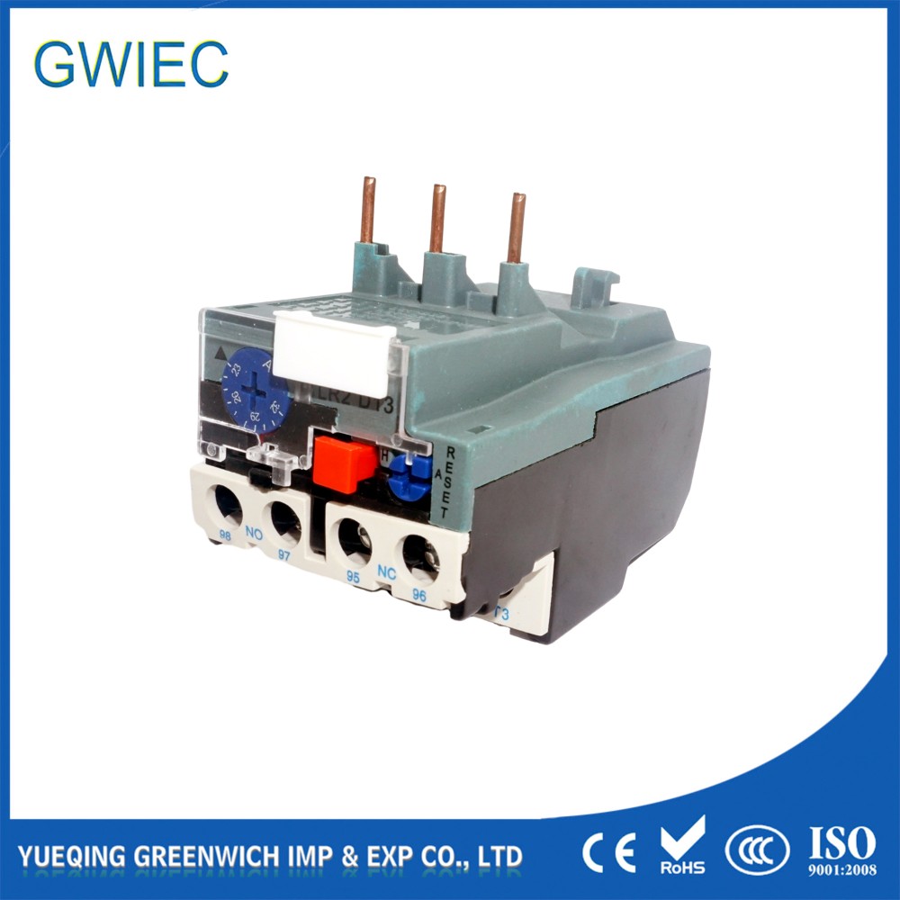
Step 3: Inspect the Panel Indicators. Look closely at the device faceplate. Locate the green trip indicator to confirm the popped state. Then, find the blue or black reset button.
Step 4: Execute the Reset. Press the reset button firmly inward. You must press until you feel a distinct mechanical "click". This tactile feedback confirms the bimetallic strips have successfully re-engaged the internal spring latch.
Step 5: Restart and Monitor. Re-energize the system cautiously. Immediately monitor the active current draw using a reliable clamp meter. Verify the running current stays well within the nameplate parameters.
3 Methods to Test a Thermal Overload Relay for Reliability
Regularly validating your protection devices ensures the safety circuit remains completely intact. Proactive testing verifies basic operational functionality. It also confirms trip timing accuracy and overall internal circuitry health. You cannot assume a component works simply because the plastic casing looks undamaged.
This is your quickest field diagnostic tool. Use it during routine weekly equipment walk-throughs.
Action: Press the physical 'Test' button located on the faceplate. Manufacturers usually color this button red for visibility.
Expected Outcome: It should mechanically trip the internal spring mechanism. The visual trip indicator will pop out instantly. The main control circuit will open, shutting down the contactor.
The Digital Multimeter Continuity Test (Standard Diagnostic)
This method provides empirical data regarding the health of your internal electrical contacts.
Preparation: Power down the entire system safely. Disconnect the control wires carefully to avoid false readings. Set your digital multimeter to the Ohms or Continuity setting.
Baseline Check: Probe terminals 95 and 96. These represent the Normally Closed (NC) contacts. They should read exactly 0 Ohms. Next, probe terminals 97 and 98. These represent the Normally Open (NO) contacts. They should read Open Loop (OL).
Trip Simulation Check: Press the manual test button again. Terminals 95 and 96 should instantly switch to OL. Terminals 97 and 98 should switch to full continuity (0 Ohms). Failure to switch indicates dangerous welded contacts or total internal mechanical failure.
Primary Current Injection Testing (Compliance-Level)
Facilities perform this rigorous test during annual turnarounds or major compliance audits.
Action: Connect a dedicated testing kit to the unit. You will inject a controlled high current directly through the main load poles. Testers typically inject 200% of the normal FLA setting.
Expected Outcome: You must verify the time-to-trip aligns perfectly with the specified trip class curve. Industrial standards define curves like Class 10 or Class 20. If it trips too slowly, the unit requires immediate replacement.
Thermal vs. Electronic Overload Relays: Is It Time to Upgrade?
Eventually, maintenance managers must evaluate whether legacy bimetallic protection remains sufficient. Modern industrial operations often require the extreme precision of solid-state technology. Upgrading an aging component can solve numerous chronic reliability issues across your plant floor.
Understanding the distinct solution categories helps you make informed engineering decisions. Let us look at the key evaluation dimensions in a structured comparison chart below.
Evaluation Dimension | Traditional Thermal Relay | Solid-State Electronic Relay |
Trigger Mechanism | Bimetallic heat deflection (physical bending) | Current transformers and microprocessors |
Accuracy & Responsiveness | Standard tolerances; slower response | Extremely tight tolerances; rapid response |
Environmental Sensitivity | Affected by high ambient room temperatures | Operates entirely independently of ambient heat |
Cost to Value Ratio | Highly cost-effective for standard applications | Higher initial CapEx but reduces nuisance trips |
Electronic variants offer unparalleled protection for high-value or highly sensitive equipment. They provide tighter trip tolerances and much faster response times. Conversely, traditional units remain robust and reliable for simpler, everyday industrial applications.
Apply simple shortlisting logic when planning plant upgrades. Transition to electronic relays if your facility experiences frequent phase loss events. Upgrade immediately if you require remote data monitoring capabilities. You should also switch if your heavy equipment operates in locations experiencing extreme ambient temperature fluctuations.
Proactive Maintenance to Prevent Nuisance Tripping
Extending the lifespan of your control panel components requires standardized preventive maintenance routines. Proactive care stops minor electrical variations before they cause unpredicted downtime. Consistent maintenance scales easily across large, complex industrial facilities.
Core Maintenance Actions
Implement these exact practices to maintain a highly reliable safety circuit:
Tightening Connections: Micro-vibrations occur constantly from nearby contactor cycling. These continuous vibrations loosen terminal screws slowly over time. Loose wires increase electrical resistance at the joint. This generates localized heat, forcing the device to false-trip repeatedly. Check all torque specifications regularly.
Environmental Cleaning: Dust, powder, and industrial grime act like thick insulation. They coat the exterior casing and trap internal heat securely. This accidental insulation alters the device's thermal calibration significantly. Use dry compressed air or non-conductive brushes to keep all panel components spotless.
Visual Inspections: Conduct routine visual checks across the entire enclosure. Look for dark discoloration, melted plastic housings, or severe pitting around the main terminals. These visual cues represent early warning signs of impending catastrophic failure.
Conclusion
A reliable protection circuit serves as your most critical line of defense against electrical fires and broken equipment. Proper reset procedures respect the hardware's inherent thermal limits. Utilizing multimeters and injection testing validates the unit's operational readiness. Never treat a panel trip casually or bypass the protection circuit.
If a component ever fails the digital multimeter continuity test, act quickly. Similarly, if you must max out the FLA dial just to hold a normal running load, immediately isolate the component. Source a direct replacement before the shift ends. Always evaluate solid-state alternatives if your facility's operational demands have scaled up significantly over the past few years.
FAQ
Q: Can a thermal overload relay reset itself automatically?
A: Yes, if the selector dial is set to "Auto". However, manual reset is strongly recommended for critical applications to force an operator inspection before the motor unexpectedly restarts.
Q: How do I know if the motor is cool enough to reset the relay?
A: The relay's bimetallic strips are engineered with a specific "thermal time constant." Once the relay itself cools enough to allow the reset latch to catch (typically 5-10 minutes), it indicates the motor has also shed its critical heat.
Q: What does the amp setting dial actually do?
A: It calibrates the exact trip threshold, aligning the relay with the specific Full Load Amperage (FLA) printed on the motor's nameplate.
Q: Can I bypass a tripping overload relay to keep production running?
A: Never. Bypassing removes the sole layer of overcurrent protection, guaranteeing imminent motor burnout and creating severe fire and arc flash hazards.


