Motor burnouts directly cause severe operational downtime and trigger heavy replacement costs across industrial facilities. Most of these catastrophic failures do not happen randomly. They often stem from incorrectly sized or improperly adjusted thermal overload relays installed in the control panel. Overlooking these critical components compromises the safety of your entire electrical infrastructure.
Effective protection requires engineers to move beyond guesswork. We must precisely align relay specifications with the motor’s Full Load Amperage (FLA), its Service Factor (SF), and the specific operational environment. Relying on default settings or outdated rules of thumb is a guaranteed path to equipment failure. Industrial automation demands exact mathematical precision to maintain continuous operation.
This guide provides a definitive framework for evaluating, selecting, and configuring the right protection equipment. You will learn how to apply standard-compliant NEC and IEC rules to your setup accurately. Facility managers and electricians will discover practical steps to configure the correct device and eliminate destructive nuisance tripping permanently.
Key Takeaways
Adhere to Absolute Maximums: NEC 430.32 dictates a maximum trip setting of 125% for motors with a Service Factor $\ge$ 1.15, and 115% for all others.
Dial Calibration Realities: Modern thermal overload relays often have the 125% safety factor built into the dial calibration—setting it higher artificially guarantees motor degradation.
The VFD Trap: Variable Frequency Drives (VFDs) require an exact 100% FLA input; manually multiplying by an SF creates a compound error that renders protection useless.
Mechanical Limits: Adjusting an overload relay upward to stop nuisance tripping is a dangerous band-aid for an undersized motor or mechanical binding.
The Engineering Baseline: Navigating FLA, Service Factor, and NEC Rules
To protect industrial motors successfully, we must fundamentally understand two core operational metrics. Full Load Amperage (FLA) represents the exact continuous current the motor draws when operating at its rated power under ideal conditions. You will find this foundational base metric permanently stamped on the motor nameplate. The Service Factor (SF) provides a different function entirely. It acts strictly as a short-term operational buffer to handle transient anomalies. It is not a continuous run rating. You should only utilize the SF to handle brief voltage drops or temporary mechanical overloads without immediately tripping the circuit.
The National Electrical Code (NEC) outlines legal thresholds for equipment safety. Under NEC 430.32, guidelines dictate maximum allowable limits to prevent fires and catastrophic electrical shorts. For motors possessing an SF of 1.15 or higher, the code allows a maximum trip setting of 125% of the nameplate FLA. For standard duty motors with a 1.0 SF, the regulatory ceiling drops down to 115%. These are absolute legal maximums designed to protect the facility, not suggestions for peak performance.
Engineers must carefully assess the risks of running equipment continuously in the designated SF zone. Heat degrades winding insulation rapidly over time. Designing a mechanical system to exploit the 1.15 SF multiplier permanently accelerates insulation breakdown drastically. Every ten degrees Celsius above the rated temperature limit halves the operational life of the motor insulation. The NEC standard serves purely as a safety ceiling. It is never an operational target for daily production cycles.
We must also evaluate "hard start" conditions carefully. Some heavy-inertia loads, like massive industrial centrifuges, require extensive acceleration periods. During these prolonged startups, standard NEC settings might trip the contactor prematurely. The NEC permits bumping protection thresholds up to 140% for SF ≥ 1.15 motors, and 130% for others. However, you should only invoke these allowances when standard settings fail repeatedly. Strict criteria govern this practice. You must verify wire sizing and contactor capacity before ever adjusting the dial to these extreme limits.
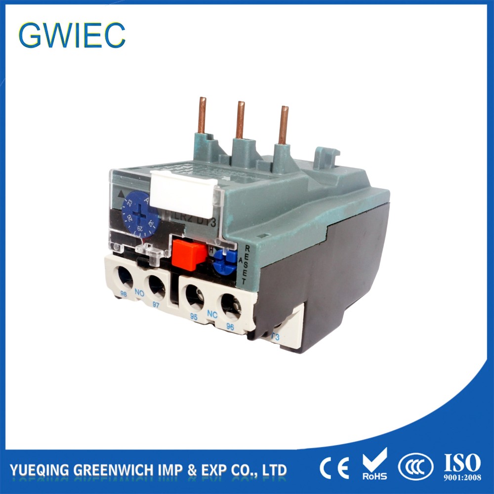
Thermal vs. Electronic Overload Protection Devices: Evaluation Criteria
Engineers must choose between two primary solution categories when designing control panels. We compare traditional bimetallic thermal overload relay units against modern electronic solid-state models. Each technology presents distinct operational strengths and specific mechanical limitations.
Standard thermal relays rely on internal bimetallic strips. These strips bend predictably as electrical current generates heat. They are highly cost-effective and remarkably reliable for standard Direct-On-Line (DOL) pumping applications. A key strength is their physical thermal memory. The bending metal accurately mimics the actual heating and cooling cycles occurring inside the motor windings. However, they carry distinct limitations. Traditional bimetallic devices lose precision in extreme ambient temperatures. They respond to panel heat just as they respond to motor current. They require specific compensation features if the motor and panel sit in vastly different climate zones.
Electronic solid-state relays provide a vastly different engineering approach. They utilize internal current transformers (CTs) and microprocessors to monitor amperage mathematically. They deliver exceptional precision and remain completely immune to ambient temperature fluctuations inside the enclosure. These units offer adjustable trip classes, allowing you to select Class 10, 20, or 30 dynamically. They also feature highly sensitive built-in phase-loss detection mechanisms.
We evaluate these electronic units through a broader operational lens. They present a noticeably higher upfront hardware cost. However, they offer a vastly superior return on investment. You will absolutely need an electronic overload protection device for variable-load motors or complex applications requiring deep diagnostic data logging. Modern industrial facilities increasingly specify these solid-state units for critical infrastructure protection.
Sizing and Dial Configuration Methodologies for DOL Systems
Industry confusion frequently surrounds physical dial settings on protection hardware. Many inexperienced technicians mistakenly perform manual math. They calculate a 125% increase over the FLA and force the dial to that higher number. You must understand how manufacturer calibration works to avoid this hazard. Modern standard relays compliant with IEC/UL 60947-4-1 usually have the safety trip factor built directly into the dial's mechanics. The numerical value you see on the face plate represents the actual motor FLA, not the ultimate trip point.
We apply a strict step-by-step configuration logic for DOL systems to guarantee accuracy:
Locate the exact FLA and the SF rating physically stamped on the motor nameplate.
Verify the manufacturer datasheet to confirm if the device features built-in dial calibration.
For standard 1.15 SF motors, set the adjustment dial exactly to match the nameplate FLA.
For 1.0 SF motors, derate the dial manually. Turn the knob counterclockwise by a half-step to satisfy the strict 115% NEMA/IEC requirement.
You also need to match trip classes to your specific mechanical application. Trip classes define the fundamental time-current characteristics of the protection circuit. A Class 10 relay forces a trip within 10 seconds when facing 600% of the motor's rated FLA. We use this profile for standard pumps and rotary compressors.
A Class 20 relay extends the limit, tripping within 20 seconds at 600% FLA. We select Class 20 specifically for high-inertia loads. Large ventilation fans need more time to reach their operating RPM without triggering an alarm. Class 30 permits up to 30 seconds for the most demanding, heavy-duty industrial startups.
| | Standard Trip Class Configuration Chart |
Trip Class | Maximum Trip Time (at 600% FLA) | Typical Industrial Application |
Class 10 | 10 Seconds | Standard water pumps, light conveyors, rotary compressors |
Class 20 | 20 Seconds | High-inertia loads, large industrial fans, heavy mixers |
Class 30 | 30 Seconds | Centrifuges, heavy rock crushers, massive stamping presses |
The VFD Exception: Avoiding the "Compound Multiplier" Trap
Variable Frequency Drives (VFDs) fundamentally alter motor control logic. They act entirely as their own dedicated overload protection device. This advanced technology introduces significant implementation risks if engineers misunderstand the setup parameters. You must treat VFD parameter configurations completely differently than standard direct-on-line contactors.
The most fatal error is falling into the "compound multiplier" trap. Technicians sometimes manually calculate a 125% multiplier before inputting the FLA into the digital VFD interface. The VFD's internal software algorithm inherently applies standard NEC multipliers automatically. Altering the input data creates a dangerous compound multiplier. For example, manually multiplying 125% by the drive's internal 125% equals a 156% threshold. Entering this inflated number entirely voids the protection circuit. The motor will inevitably burn to the ground long before the drive recognizes a fault.
We must also strictly enforce service factor negation. You must treat all VFD-driven motors as having an operational SF of 1.0, regardless of the nameplate. Variable frequency drives use Pulse Width Modulation (PWM) to control speed. PWM introduces severe electrical harmonics directly into the motor windings. These high-frequency harmonics generate substantial additional thermal stress. Furthermore, running a motor at slower speeds reduces the cooling fan's efficiency. Because of this extra localized heat, the motor entirely loses its traditional physical SF buffer. Always input the raw, unadjusted nameplate FLA into the drive parameters and let the internal algorithm manage the multipliers.
Environmental Variables and Troubleshooting "Nuisance" Tripping
Environmental variables constantly complicate motor protection strategies. Ambient temperature compensation represents a critical environmental factor. If a motor operates outdoors in sub-zero weather while its control panel sits inside a heated electrical room, conventional bimetallic relays fail. The relay simply cools at a different rate than the motor housing.
You must shortlist specific hardware criteria for these disjointed scenarios. Ambient-compensated bimetallic relays or advanced electronic solid-state relays are strictly required here. They utilize secondary compensation loops to decouple the ambient panel temperature from the motor's actual thermal state.
Nuisance tripping continuously frustrates production and maintenance teams. We rely on the "fever" analogy in troubleshooting to explain this phenomenon. Increasing the overload setting to bypass a persistent nuisance trip is exactly like raising a thermometer's scale to cure a severe fever. The underlying mechanical disease remains untreated. You simply silence the safety alarm while the equipment actively burns.
Always execute a strict root cause protocol. Force a comprehensive mechanical review before you ever adjust electrical leniency parameters.
Check the physical motor for severe bearing friction or imminent mechanical failure.
Inspect fluid lines thoroughly for pump blockages, sludge buildup, or valve restrictions.
Verify the motor size is not fundamentally undersized for the current production load.
Measure incoming voltage phases for severe power unbalance or transient voltage dips.
By investigating these mechanical constraints first, you actively protect the equipment and seamlessly comply with mandatory safety codes.
Conclusion
Properly sizing your thermal protection hardware guarantees operational safety and maximizes equipment longevity. Base all panel sizing decisions purely on exact nameplate FLA values. Respect the absolute thermal limits defined by the standard Service Factor. Choose modern electronic relays for high-value assets or highly variable operational loads. Above all, strictly adhere to NEC and IEC dial configuration realities to prevent dangerous thermal conditions inside your plant.
For your immediate next steps, conduct a comprehensive audit of your current motor control panels. Actively search the VFD parameters for dangerous "compound multiplier" errors. Always consult the specific manufacturer data sheets to verify proprietary dial calibration curves before initiating final panel commissioning.
FAQ
Q: Can I use a single thermal overload relay to protect multiple motors?
A: No. Each motor requires dedicated individual protection mapped directly to its specific FLA and mechanical load characteristics. Grouping motors under one relay violates safety codes and guarantees uneven protection, leading to severe equipment damage.
Q: How do I calculate my thermal overload relay size if the nameplate only lists kW or HP?
A: You can derive FLA using the standard formula: FLA = (kW * 1000) / (V * 1.732 * cos φ). However, field measurements or consulting the exact manufacturer data sheet is always preferred over theoretical mathematical calculation.
Q: What is the correct overload setting for a motor with a 1.0 Service Factor?
A: Per NEC guidelines, a 1.0 SF motor must be protected at a maximum of 115% of its FLA. Depending on the specific relay brand and calibration, this typically requires setting the physical dial slightly below the stated nominal marks.


