Facility managers and engineers face a complex balancing act every day. You need to eliminate heavy utility penalties from your monthly bills. You also want to free up existing transformer capacity immediately. However, you must avoid deploying a reactive power system prone to overcorrection or premature burnout. Choosing between fixed and automatic power factor correction dictates your upfront capital expenditure. It also directly impacts your long-term maintenance overhead. We will explore both architectural choices to help you decide.
Electrical infrastructure requires absolute precision. Making the wrong choice leads to costly downtime and ruined equipment. We will highlight a critical, often-overlooked failure point in dynamic networks. This weak link is the switching hardware. Standard components often fail under heavy electrical surges. We will show you why upgrading specific parts secures your entire investment. By the end of this guide, you will understand exactly how to match your equipment to your facility's unique load profile.
Key Takeaways
The 70% Rule: If facility loads remain constant for more than 70% of the operating hours, fixed capacitor banks offer the highest ROI; otherwise, APFC is required.
Overcorrection Risks: Applying fixed compensation to variable loads can cause leading power factor and dangerous voltage surges.
Component Survival: Standard contactors degrade rapidly under the extreme inrush currents of capacitor switching; specialized capacitor contactors with damping resistors are mandatory for APFC durability.
Harmonic Threats: Non-linear loads (VFDs, UPS) require detuned reactors regardless of whether the system is fixed or automatic to prevent parallel resonance.
The Business Case: When to Correct (and When to Hold Off)
Utility bills often hide the true cost of poor electrical efficiency. Most industrial equipment relies on magnetic fields to operate. Motors, transformers, and relays draw reactive power (kVAR) alongside working power (kW). Utilities must supply the total apparent power (kVA). If your reactive power demand is high, you strain the entire electrical grid. You must evaluate your specific operational data before buying hardware.
When to deploy correction:
You consistently pay kVA or kVAR utility penalties. Many providers charge steep peak demand fees based on your highest 15-minute usage window.
Your transformer capacity is maxed out by current (Amps). The transformer might run hot even when actual mechanical work (kW) remains below limits.
You experience high I⊃2;R losses in trailing cables. These thermal losses result in severe voltage drops at the load end.
You want to add new machinery without buying a larger utility transformer.
When to hold off or pivot strategy:
Your "low power factor" is actually distortion power factor. Harmonics drive this distortion, not reactive power. Standard capacitors will not fix this. You need active harmonic filtering.
You are attempting to fix brief transient sags. Across-the-line motor starts cause massive, temporary voltage drops. Steady-state correction cannot solve dynamic starting issues.
Your facility maintains a natural power factor above 0.95. Adding capacitors here yields diminishing financial returns.
Fixed Power Factor Correction: Best for Constant Baseline Loads
Fixed compensation offers a straightforward approach to managing reactive power. The mechanism is simple. You hardwire the capacitors directly into the electrical system. You can connect them at the main switchgear or at specific motor terminals. They provide a constant, unchanging kVAR output whenever energized.
Advantages of Fixed Systems:
Lowest Initial CapEx: Fixed units lack complex controllers. They cost significantly less to purchase and install.
Minimal Maintenance Footprint: They operate without microprocessors or frequent switching cycles. This simplicity reduces routine maintenance needs.
High Reliability: The lack of moving parts ensures long-term stability under constant load conditions.
Localized Benefits: Installing them at the motor level reduces cable heating across your entire distribution network.
Implementation Risks (The Overcorrection Problem):
Fixed systems pose severe risks in dynamic environments. Imagine your facility's inductive load drops during a shift change. If the fixed capacitor remains online, the system achieves a leading power factor. This condition causes dangerous voltage spikes. These surges easily damage sensitive electronics, variable frequency drives, and lighting ballasts. You must size fixed units carefully. Never exceed the no-load reactive requirement of the motor.
Ideal Deployment Scenarios:
Fixed banks thrive in predictable environments. Continuous process motors benefit greatly from local compensation. Constant-load municipal water pumps also serve as perfect candidates. Dedicated lighting circuits in large warehouses match the fixed output perfectly. If the load runs 24/7 at a steady pace, fixed correction wins.
Automatic Power Factor Correction (APFC): Sizing for Dynamic Environments
Modern industrial facilities rarely maintain constant electrical loads. Automatic Power Factor Correction (APFC) systems adapt to these dynamic environments. The mechanism relies on microprocessor-based reactive power controllers. These intelligent relays continuously monitor the network's power triangle. They calculate your real-time kVAR demand. The controller then steps various capacitor banks in or out to match this demand perfectly.
Advantages of APFC:
An automatic panel maintains a highly precise target PF. Usually, facility engineers set this target between 0.95 and 0.99. The system handles fluctuating loads seamlessly. If a large compressor turns off, the controller immediately disconnects a capacitor step. This dynamic response fully eliminates the risk of over-voltage from overcorrection. It protects your downstream equipment while keeping utility penalties at zero.
Implementation Risks:
Automatic systems require higher upfront capital costs. They also demand a larger physical footprint in your electrical room. Because the panel constantly reacts to load changes, electromechanical switching components suffer increased wear. You must budget for periodic inspections. You will eventually need to replace worn switching elements.
Ideal Deployment Scenarios:
Variable environments demand automatic stepping. Manufacturing plants with frequent shift changes rely on APFC. Heavy fabrication shops using welding machines require dynamic tracking. Mixed-use commercial facilities, like large shopping malls, also benefit from automatic adjustments. Whenever load profiles change hourly, automatic compensation is the only safe choice.
Feature Comparison Chart
Feature | Fixed Capacitor Banks | Automatic (APFC) Panels |
Load Adaptability | None. Output is constant. | High. Steps adjust automatically. |
Over-voltage Risk | High risk during light load periods. | Zero risk. Controller prevents overcorrection. |
Capital Expenditure | Low initial cost. | Moderate to high initial cost. |
Maintenance Needs | Minimal. Visual checks suffice. | Moderate. Requires contactor and relay checks. |
Target Application | Pumps, fans, continuous motors. | Stamping presses, mixed-use buildings. |
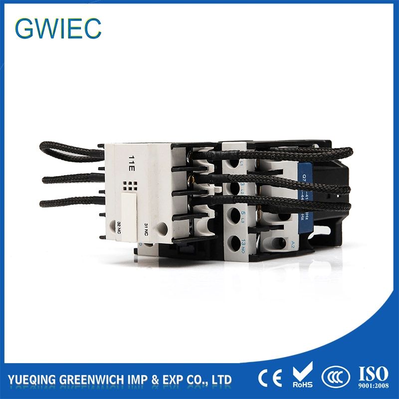
The switching hardware forms the beating heart of any dynamic correction panel. Standard electrical components fail miserably in these applications. The root cause is the extreme inrush current problem. Energizing a discharged capacitor creates a massive, instantaneous peak transient current. This surge happens in milliseconds. It can easily reach up to 200 times the nominal current rating of the circuit.
Standard electrical contactors cannot survive this violent surge. Their metal contacts literally weld together under the intense heat. When contacts weld closed, the capacitor remains permanently engaged. This defeats the purpose of an automatic panel. It quickly leads to the very overcorrection you tried to avoid.
Why Specialized Hardware is Required:
You must use components engineered for this specific punishment. Specialized units feature pre-charge modules. These modules utilize tungsten damping resistors. The mechanism works in a precise sequence. First, the pre-charge contacts close. Current flows through the damping resistors. This action artificially limits the massive inrush surge. Milliseconds later, the main contacts close to carry the continuous load. Finally, the pre-charge contacts open. This engineering marvel protects the entire circuit. Installing a dedicated capacitor contactor is strictly mandatory for panel durability.
This staged engagement extends the lifespan of the Automatic Power Factor Correction panel. It also protects the individual low-voltage capacitors from internal dielectric damage.
Advanced Alternatives for Extreme Duty:
Some environments feature ultra-fast cycling. Robotic spot welding lines create rapid, aggressive load changes every few seconds. Mechanical contacts will wear out quickly here, even with damping resistors. For these applications, replace electromechanical units with solid-state static contactors. These advanced devices use thyristors instead of physical contacts. Thyristors enable blazing 40-millisecond response times. They eliminate switching transients entirely. They operate silently and require zero mechanical maintenance.
Harmonics and Hardware Survival: Avoiding Parallel Resonance
Modern electrical environments present new threats to hardware survival. You must avoid parallel resonance at all costs. Facilities now use more non-linear loads than ever before. Variable Frequency Drives (VFDs), EV chargers, and LED lighting drivers dominate modern grids. These devices draw current in short, abrupt pulses rather than smooth sine waves. If these non-linear loads exceed 30% of your total facility load, they generate severe harmonic distortion.
The Resonance Trap:
Standard capacitors cannot handle heavy harmonics. The 5th and 7th harmonic frequencies prove particularly destructive. Standard capacitors form a parallel resonant circuit with your utility transformer's natural inductance. This accidental circuit amplifies existing harmonics exponentially. The capacitors act as a sink for this amplified high-frequency energy. They swell, overheat, and eventually rupture. The switching components also melt down under the extreme thermal stress.
The Engineering Solution:
The solution requires careful system design. You must integrate detuned series reactors into your APFC or fixed bank. Engineers typically specify 7% or 14% impedance reactors. These heavy iron-core reactors shift the system's resonance frequency. They push it safely below the lowest dominant harmonic order. For example, a 7% reactor shifts resonance below the 5th harmonic. This strategy protects your capacitors and contactors. It ensures long-term survival while maintaining excellent power factor correction.
Decision Matrix: Shortlisting the Right Architecture
Selecting the right architecture requires a logical decision process. We have defined three common facility scenarios. Matching your facility to the correct scenario prevents wasted capital.
Scenario A: Constant Load, Budget Constrained
You operate continuous pumps or large ventilation fans. You have a limited CapEx budget. Install fixed capacitors directly at the motor starter. Ensure your kVAR sizing does not exceed 90% of the motor's no-load reactive requirement. This prevents dangerous self-excitation when you disconnect the motor from the grid.
Scenario B: Variable Load, Standard Motors
You run a manufacturing floor with shifting loads. You primarily use standard induction motors without VFDs. Engineers often upgrade the main switchboard for these environments. By utilizing a heavy-duty capacitor contactor,Automatic Power Factor Correction architectures manage variable loads flawlessly. Install this centralized APFC unit at your main incoming feed. It will step banks in and out as factory demand shifts.
Scenario C: Variable Load, Heavy VFD Usage
Your facility relies heavily on automated robotics, VFDs, and large UPS systems. Non-linear loads dominate your electrical profile. You must deploy a detuned APFC system. This configuration safely corrects your power factor. It simultaneously protects all sensitive panel components from destructive harmonic resonance.
Architectural Selection Matrix
Facility Load Profile | Harmonic Presence | Recommended Architecture | Key Component Focus |
Constant (>70% time) | Low (<15% THDi) | Fixed Capacitor Bank | Standard heavy-duty wiring. |
Variable (Shift based) | Low (<15% THDi) | Standard APFC Panel | Damping resistor contactors. |
Variable (Automated) | High (>30% THDi) | Detuned APFC Panel | 7% or 14% Series Reactors. |
Ultra-fast Cycling | Varies | Static APFC Panel | Solid-state Thyristors. |
ROI Expectation:
Properly specified correction systems yield excellent financial returns. Most facilities reach full payback within 8 to 24 months. You achieve this rapid return by entirely eliminating utility penalty charges. You also recover trapped system capacity. This recovered capacity often allows you to delay or cancel expensive transformer upgrades.
Conclusion
The choice between fixed and automatic systems relies entirely on your facility's operational habits. Load variability and electrical topology dictate the correct answer. If your load fluctuates throughout the day, automatic systems provide crucial safety. They prevent dangerous overvoltage conditions. If your load remains steady round-the-clock, fixed systems save you significant money upfront.
System reliability hinges heavily on proper component selection. You must invest in robust switching hardware. Standard contactors will fail quickly under capacitive loads. Upgrading to specialized switching elements ensures panel longevity. Furthermore, detuning reactors are non-negotiable if your facility utilizes modern non-linear loads.
We highly recommend conducting a comprehensive power quality audit. Measure your precise kVAR needs at the main incoming feed. Evaluate your harmonic profiles thoroughly using a power quality analyzer. Do this before writing a hardware specification. Engineering precision ensures safety, prevents early equipment failure, and maximizes your financial return.
FAQ
Q: Why do we use capacitors instead of inductors for power factor correction?
A: Most industrial loads are heavily inductive. Motors and transformers cause current to lag behind voltage. Remember the "ELI the ICE man" concept. In an inductor (L), voltage (E) leads current (I). In a capacitor (C), current (I) leads voltage (E). Capacitors supply capacitive reactive power. This current-leading effect perfectly cancels out the inductive lag, bringing the power factor closer to unity.
Q: Can I install a fixed capacitor directly on a VFD output?
A: No. This poses a massive engineering risk. Connecting standard capacitors to the non-sinusoidal output of a Variable Frequency Drive causes immediate damage. The drive will fault or fail completely. The capacitor will overheat and likely rupture instantly. You must always install power factor correction upstream of the VFD on the main line side.
A: You should establish a practical, consistent maintenance baseline. Perform visual and thermal inspections every 6 to 12 months. Look for pitted contacts. Check for failed damping resistors. Use an infrared camera to identify excess heat build-up. Catching early wear prevents catastrophic panel failure and avoids highly expensive facility downtime.


