Are you a facility manager or an electrical engineer struggling to diagnose unexplained motor shutdowns? Nuisance tripping is rarely just a minor annoyance you can ignore. It frequently points to underlying system friction, power quality degradation, or poor selective coordination. Let us define the reality of nuisance tripping. It occurs when your equipment shuts down without a genuine locked-rotor or critical overload event. Engineers often assume the hardware failed. However, a thermal overload relay is rarely "broken." It is usually doing its job perfectly inside an unoptimized environment.
Permanently resolving these intermittent trips requires a better approach. You must move beyond the unreliable "reset-and-pray" method. Modern facility management demands a data-driven electrical and mechanical troubleshooting framework. In this article, you will learn how to identify masked mechanical wear. We will examine how poor power quality affects relays. You will also discover how to apply actionable solutions to stabilize your motor control centers.
Key Takeaways
Nuisance trips are typically traced back to four root categories: incorrect configuration, poor power quality, adverse ambient environments, or hidden mechanical wear.
Integrating Variable Frequency Drives (VFDs) with standard bimetallic relays frequently causes harmonic heating, necessitating specialized filtering or hardware upgrades.
Persistent tripping often justifies an upgrade from legacy thermal devices to a digital motor protection relay with advanced diagnostics and ambient temperature immunity.
Proper selective coordination using Time-Current Characteristic Curves (TCCs) is non-negotiable for reliable system operation.
The Hidden Costs of Nuisance Tripping on Facility Operations
Nuisance tripping creates ripple effects across your entire facility. You cannot view a tripped relay as an isolated event. It is a business problem demanding immediate attention.
Production Downtime & Mechanical Wear
Every time a relay trips unnecessarily, production stops abruptly. Repeated hard stops severely degrade motor insulation. They also increase mechanical fatigue on your couplings and drive belts. Frequent motor restarts introduce massive inrush currents. These recurring current spikes generate excess heat. Ultimately, this heat accelerates the deterioration of internal motor components.
Cascaded Tripping & System Imbalance
A single localized trip often creates broader electrical chaos. When a large motor goes offline unexpectedly, it causes temporary three-phase imbalances. These sudden voltage fluctuations echo through your distribution panel. They can easily trigger cascading trips in upstream protective devices. Your local issue suddenly becomes a facility-wide power failure.
Utility Compliance (SAIFI/MAIFI)
Larger industrial facilities face regulatory scrutiny. Poor selective coordination leads to frequent main breaker trips. These interruptions directly impact utility reliability metrics. Regulators monitor metrics like SAIFI (System Average Interruption Frequency Index) and MAIFI (Momentary Average Interruption Frequency Index). Violating these metrics risks severe regulatory penalties. Maintaining a stable relay network ensures you stay compliant.
Core Engineering and Operational Causes of Unwarranted Tripping
To eliminate nuisance tripping, we must classify the root causes. Use this categorized diagnostic framework to structure your investigation.
Configuration & Selection Errors
Many relays trip because engineers configure them incorrectly during installation. Two common mistakes dominate this category.
Mismatched Trip Class: Engineers sometimes use a Class 10 relay for a high-inertia load. High-inertia equipment, like industrial crushers, requires a Class 30 relay to accommodate longer startup times.
Incorrect FLA Settings: Technicians frequently set the Full Load Amps (FLA) dial incorrectly. They often fail to account for the motor’s Service Factor. This oversight dramatically shrinks the operational safety margin.
Power Quality and Supply Asymmetry
Your relay assumes it receives perfect electrical power. Reality often proves otherwise.
Phase Imbalance: Consider a widely accepted industry rule of thumb. A mere 2–3% voltage imbalance can cause up to a 20% increase in current on a single phase. This localized current spike generates excessive heat, causing premature tripping.
Undervoltage Conditions: When grid voltage drops, your motor fights to maintain torque. It achieves this by drawing higher current. The relay detects this current increase and trips the circuit.
Ambient Temperature & Environmental Constraints
Standard relays rely on physical heat to trigger. Environmental heat directly interferes with this mechanism.
Enclosure Heat: Sealed NEMA-rated enclosures trap heat effectively. This accumulated ambient heat severely limits the thermal margin of bimetallic strips. The relay trips even when the motor runs normally.
Lack of Compensation: Older or budget-tier relays lack ambient temperature compensation. They cannot distinguish between motor-generated heat and scorching summer weather.
Masked Mechanical Overloads
Sometimes the electrical system works perfectly, but the machine struggles physically. Bearing degradation, shaft misalignment, and pump blockages create severe mechanical friction. The motor draws more current to overcome this physical resistance. The relay reads this strictly as an overcurrent event and trips.
The VFD Variable: High-Frequency Harmonics and Cable Issues
Integrating Variable Frequency Drives (VFDs) introduces complex electrical variables. Standard relays struggle to process VFD output reliably.
Harmonic Heating
VFDs utilize Pulse Width Modulation (PWM) to control motor speed. They operate at carrier frequencies ranging between 2 and 16 kHz. This high-frequency operation generates non-torque-producing harmonic currents. These harmonics artificially heat standard bimetallic elements. The relay interprets this harmonic heat as a dangerous overload. It trips unnecessarily.
Capacitive Charging Currents
Facilities often use long cable runs exceeding 50 meters. Long cables create high dV/dt (voltage change over time) scenarios. This rapid voltage switching causes capacitive leakage. High charging currents pass through the relay but never reach the motor. The relay measures higher current than the motor actually consumes, triggering a false positive trip.
Mitigation Options
You must evaluate mitigation solutions based on cost and effectiveness. We summarize the most effective strategies below.
Solution Type | Effectiveness | Implementation Complexity |
Load-Side Line Reactors | Moderate. Reduces dV/dt spikes but does not eliminate all harmonic heat. | Low. Easy to retrofit into existing control panels. |
Sine Wave Filters | High. Converts PWM output back to a near-perfect sine wave. | Medium. Requires more physical space and higher initial investment. |
Solid-State Overload Relay Upgrade | Very High. Immune to harmonic heating and high-frequency noise. | Low. Direct replacement for existing bimetallic devices. |
Troubleshooting Framework: Isolating the Root Cause
You need actionable evaluation criteria to isolate nuisance tripping. Avoid guessing. Follow this systematic troubleshooting framework.
Step 1: Safe Physical Inspection. You must mandate strict safety protocols. Lock out power and perform zero voltage verification. Inspect the equipment visually. Look for burned contacts or melted plastic. Check for loose terminal connections. Loose wires generate independent heat, fooling the bimetallic strip. Also, verify proper wire sizing to ensure adequate heat dissipation.
Step 2: Operational Data Logging. Map the exact trip timing. Does the relay trip immediately during start-up? If so, this points directly to Trip Class mismatches or extreme inrush issues. Does it trip during steady-state operation? Steady-state trips usually point to ambient heat accumulation, phase imbalance, or hidden mechanical wear.
Step 3: Protection Device Coordination. You must plot Time-Current Characteristic Curves (TCCs). Ensure the overload relay settings coordinate correctly with upstream circuit breakers. Your goal is simple. You must keep transient inrush currents firmly on the left side of the curve. This prevents the upstream breaker from tripping prematurely.
When to Upgrade: Thermal vs. Electronic Motor Protection Relays
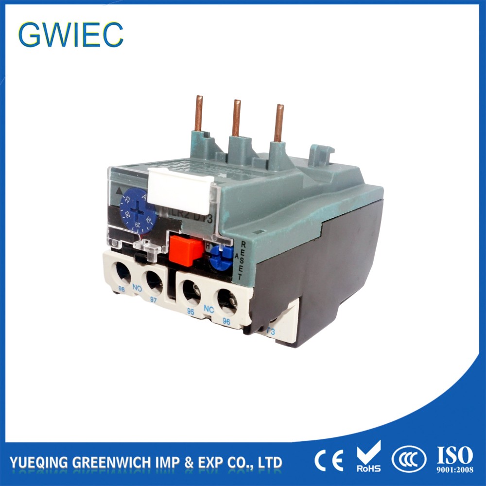
Persistent tripping forces you to evaluate your equipment stack. You must decide if your current hardware meets modern operational demands. When evaluating solutions, analyzing a standard thermal overload relay,motor protection relay setup clarifies your upgrade path.
Limitations of Thermal Relays
We acknowledge the simplicity of traditional relays. They offer highly cost-effective protection for standard applications. However, their limitations become obvious in complex environments. They remain highly vulnerable to ambient heat. Furthermore, they lack diagnostic feedback. When they trip, they leave engineers guessing about the root cause.
The Electronic Advantage
Upgrading to a modern electronic motor protection relay offers distinct advantages. Electronic relays utilize Current Transformers (CTs) to measure electricity directly. They do not rely on bimetallic heat generation. This eliminates ambient temperature variables entirely. Electronic relays also provide precise phase-loss and phase-imbalance protection. They give you the data needed to prevent the next shutdown.
ROI and Decision Logic
Provide a structured framework for equipment upgrades. Recommend retaining traditional relays for low-risk, fractional horsepower motors. Their simplicity works perfectly there. However, mandate electronic or solid-state relays for critical continuous-process equipment. You should also demand electronic protection for high-inertia loads and all VFD-driven systems. The reduction in downtime justifies the upgrade immediately.
Conclusion
A tripping relay rarely signals a broken component. It is a messenger highlighting system inefficiency. Understanding the difference between mechanical wear, environmental heat, and electrical harmonics prevents costly diagnostic errors. You now possess the framework needed to eliminate nuisance tripping permanently.
Take immediate action. Conduct a comprehensive power quality audit on your most problematic circuits. Review your motor nameplate data and verify it matches your current dial settings perfectly. Finally, evaluate your critical motor starters. Identify areas where an electronic relay upgrade will provide immediate reliability gains.
FAQ
Q: How do I safely reset a tripped thermal overload relay?
A: First, ensure power is locked out if inspecting the panel physically. Wait for the mandatory cooling period. Bimetallic strips require time to cool and return to their original shape. Once cooled, press the manual reset button firmly. For auto-reset mechanisms, the relay resets itself after cooling. Always investigate the root cause before restarting the motor.
Q: Does a thermal overload relay protect against short circuits?
A: No. It provides delayed thermal protection against sustained overcurrents. It acts too slowly to stop a short circuit. You must use instantaneous magnetic protection devices, such as circuit breakers or specialized fuses, to protect the system against short-circuit events.
Q: What does Trip Class 10, 20, and 30 mean?
A: Trip Class defines the maximum time, in seconds, a relay takes to trip when handling 600% of the motor's full load current. Class 10 trips within 10 seconds. Class 20 trips within 20 seconds. Class 30 trips within 30 seconds. Higher classes accommodate high-inertia loads.
Q: Can I test a thermal overload relay with a multimeter?
A: Yes. Disconnect the power completely. Use your multimeter to verify continuity across the Normally Closed (NC) auxiliary contacts. When the relay is cool and set properly, you should read continuity. If the relay is tripped, the NC contacts open, and your multimeter will show no continuity.


