The reliability of any electrical installation depends entirely on specifying the correct circuit protection device for the specific load and fault conditions. Misapplying these components introduces severe operational risks. Using a breaker with inadequate breaking capacity risks catastrophic failure during a massive fault. Over-specifying leads to bloated panel layouts and wasted footprint. Choosing between resettable devices and sacrificial elements directly impacts long-term maintenance downtime and operator safety on the factory floor. This technical guide evaluates MCB vs Fuse vs MCCB based on current ratings, short-circuit capacities, and operational environments. We will break down the mechanical differences and application frameworks to facilitate accurate decision-making for your electrical systems, ensuring you match the right hardware to the specific demands of your distribution boards.
Fuses: Provide the highest short-circuit breaking capacity and fastest clearing times for the lowest upfront cost, but require physical replacement after a fault, increasing downtime and requiring qualified personnel.
MCBs (Miniature Circuit Breakers): Offer resettable, convenient protection for low-voltage, low-current circuits (typically up to 125A) with fixed trip settings and dead-front safety for non-technical users.
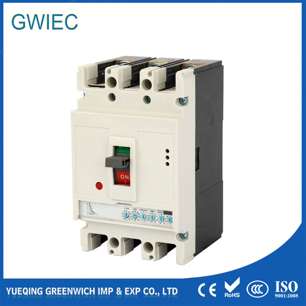
MCCBs (Moulded Case Circuit Breakers): Deliver high-capacity protection (up to 2500A+) with adjustable trip characteristics, essential for main distribution and heavy industrial loads.
Selection Driver: The final choice dictates the balance between initial capital expenditure, system downtime tolerance, multi-phase motor protection needs, and strict adherence to coordination/selectivity requirements.
Understanding the Core Circuit Protection Devices
The Traditional Fuse and Fuse Switch
A traditional fuse operates as a sacrificial thermal element designed to melt under overcurrent or short-circuit conditions. The internal construction typically consists of a calibrated silver or copper element surrounded by an arc-quenching medium, usually high-purity silica sand, housed within a ceramic body. When a fault occurs, the massive thermal energy vaporizes the metal element instantly. The silica sand absorbs the thermal shock and fuses into glass, rapidly extinguishing the electrical arc. This physical reaction provides an extremely high breaking capacity. Modern High Rupturing Capacity (HRC) fuses routinely interrupt fault currents exceeding 100kA safely.
They offer unmatched current-limiting capabilities, cutting off the fault energy before it reaches its peak. This rapid action protects sensitive downstream components like motor starters, contactors, and solid-state drives. However, the operational reality presents a distinct maintenance challenge. A blown element requires physical replacement. You must maintain accurate spare inventory on site at all times. Qualified personnel must safely extract the blown element and install the exact replacement. Pairing the element with a fuse switch mitigates many safety concerns. This combination provides a physical isolation point. Operators can safely disconnect power before opening the enclosure to replace the element, ensuring they do not interact with live busbars.
Miniature Circuit Breaker (MCB)
An electromechanical breaker utilizes two distinct mechanisms to protect a circuit. A bimetallic strip handles thermal overload protection. As current exceeds the rated value, the strip heats up and bends, eventually tripping the latching mechanism. A magnetic coil or solenoid handles instantaneous short-circuit protection. A massive fault current energizes the coil, instantly pulling the plunger to break the circuit. The primary advantage is instant resettability. Operators can flip the toggle back to the ON position after a fault clears, drastically reducing system downtime.
Manufacturers standardize these units for 35mm DIN-rail mounting. This standardization allows dense packing inside modular enclosures. Inside the casing, an arc chute consisting of parallel metal plates divides and cools the arc generated during disconnection. Despite these features, limitations exist regarding overall capacity. A miniature circuit breaker generally handles lower continuous current ratings. Most units max out at 125A. Short-circuit breaking capacities typically range from 6kA to 10kA. High-performance models might reach 15kA, but they cannot safely interrupt massive industrial fault currents. You must restrict their use to final distribution circuits and low-power control panels.
Moulded Case Circuit Breaker (MCCB)
These devices operate on similar principles to miniature versions but feature heavy-duty construction designed for severe industrial environments. The internal components sit inside a robust glass-polyester moulded case. This casing safely contains the massive pressure and heat generated when interrupting high fault currents. A moulded case circuit breaker handles high continuous currents, with standard frames ranging from 16A up to 2500A or more.
They offer adjustable thermal and magnetic trip settings, allowing engineers to fine-tune the protection profile to the specific load. Modern units feature advanced Electronic Trip Units (ETUs) with LCD screens and microprocessor control. This allows precise system coordination across complex networks. You can adjust parameters like long-time delay, short-time pickup, and instantaneous tripping thresholds. The heavy-duty construction requires a larger physical footprint. They do not snap onto standard DIN rails. You must bolt them directly to panel backplates or heavy copper busbar systems, requiring dedicated mounting hardware and specific clearance zones for arc venting.
Technical Evaluation Dimensions
Current Ratings and Tripping Characteristics
Continuous current handling varies significantly across these devices. Miniature breakers manage low currents effectively, making them ideal for lighting and small appliance circuits. Fuses scale from fractions of an amp to extremely high ratings depending on their specific class and physical size. Moulded case breakers handle medium to very high loads continuously, serving as the backbone for main distribution boards.
Fuses generally clear severe short circuits faster than mechanical breakers. The melting element reacts instantly to massive thermal energy, offering superior current limitation. Mechanical breakers require physical movement to open contacts. This mechanical inertia adds milliseconds to the clearing time. Standard miniature breakers use fixed trip curves to define their response to overcurrents.
Trip Curve
Magnetic Trip Multiple
Typical Application
Type B
3 to 5 times rated current
Resistive loads, lighting, residential wiring
Type C
5 to 10 times rated current
Inductive loads, small motors, commercial lighting
Type D
10 to 20 times rated current
High inrush loads, transformers, heavy motors
Type K / Z
Highly sensitive / specialized
Semiconductor protection, sensitive electronics
Heavy-duty breakers feature highly customizable electronic trip units. You can adjust the long-time (Ir), short-time (Isd), and instantaneous (Ii) pickup levels precisely. This flexibility allows a single breaker frame to adapt to changing load conditions without requiring physical replacement.
Short-Circuit Breaking Capacity (kA Ratings)
Breaking capacity defines the maximum fault current a device safely interrupts without destroying itself. Exceeding this rating causes the device to explode, risking a severe panel fire and arc flash incident. Fuses excel in high-fault environments. A standard industrial fuse safely clears 100kA to 120kA faults. Moulded case breakers handle substantial industrial faults, with typical ratings ranging from 25kA to over 100kA depending on the frame size and internal arc chute design.
Miniature breakers remain restricted to lower-tier fault zones, typically handling 6kA or 10kA faults. To select the right device, you must calculate the Prospective Short-Circuit Current (PSCC) at the installation point.
Determine the utility transformer kVA rating and impedance percentage.
Calculate the maximum fault current available at the transformer secondary terminals.
Calculate the impedance of the cable run from the transformer to your specific distribution panel.
Determine the attenuated fault current at the panel nodes.
Select a protection device with a breaking capacity (Icu) exceeding this calculated value.
Never install a 10kA device at a node with a 25kA prospective fault. The device will fail to clear the fault, welding its contacts closed and allowing the massive current to destroy downstream equipment.
Multi-Pole Operation and Single-Phasing Risks
Three-phase system protection requires careful evaluation of how the device handles multi-phase faults. Multi-pole mechanical breakers utilize an internal common trip bar. A fault on any single phase triggers the mechanism, disconnecting all three phases simultaneously. This action protects three-phase motors from unbalanced loads and ensures complete isolation of the circuit.
Fuses present a distinct operational risk known as single-phasing. A fault or overload might blow only one fuse in a three-phase circuit. The motor continues drawing power across the remaining two phases to maintain its mechanical output. This creates a severe current imbalance. The current in the remaining phases spikes significantly. The motor windings will rapidly overheat, degrading the insulation. The motor will fail completely unless secondary protection reacts in time. You must pair fuses with perfectly calibrated thermal overload relays or electronic motor protection relays to prevent single-phasing damage.
Auxiliary Accessories and Smart Panel Integration
Mechanical breakers support extensive control capabilities through modular accessories. You can equip them with various snap-on or internally mounted components. Auxiliary contacts provide remote status indication, sending a signal to a PLC when the breaker is open or closed. Alarm contacts specifically indicate if the breaker tripped due to a fault rather than manual operation. Shunt trips allow remote opening via a PLC command or an emergency stop button on the factory floor. Undervoltage releases trip the breaker automatically during severe power dips, preventing motors from stalling and overheating.
These accessories enable deep integration into automated control systems and SCADA networks. Traditional fuses remain entirely passive devices. They lack native smart integration. You cannot extract remote trip reporting data directly from a standard fuse element. Some modern fuse bases include microswitches for blown-fuse indication, but this remains rudimentary compared to the advanced power metering and communication modules available for electronic circuit breakers.
Reset Capabilities and System Downtime
A tripped circuit directly impacts operational continuity. Operators can immediately reset mechanical breakers once they identify and clear the fault. You simply flip the toggle switch down to the reset position, then back up to the ON position. This restores power in seconds, minimizing production losses.
Blown fuses require strict lockout/tagout (LOTO) procedures and physical intervention.
The operator must identify the blown phase using a multimeter.
Maintenance personnel must isolate the upstream power source and apply LOTO padlocks.
The technician physically extracts the blown element using specialized pullers.
They must verify the replacement matches the exact current rating, voltage rating, and clearing curve of the original.
The technician installs the new element, removes LOTO, and restores power.
This process significantly extends system downtime. Facilities without dedicated maintenance staff face longer delays, often waiting hours for an external technician to arrive with the correct replacement part.
Customization and Coordination (Selectivity)
Selectivity ensures only the device nearest the fault trips. This prevents a minor short circuit on a lighting branch from tripping the main incomer and causing a widespread power outage across the entire facility. Heavy-duty breakers provide dial-adjustable settings to achieve this. You can adjust the continuous current rating and magnetic pickup. Electronic trip units offer even finer control over time delays, allowing you to implement chronometric (time-based) and amperometric (current-based) selectivity.
Miniature breakers and fuses rely entirely on fixed time-current curves. Achieving perfect selectivity with fixed curves requires careful upstream and downstream matching. You must plot the curves on a logarithmic chart and ensure the downstream curve sits entirely below and to the left of the upstream curve. If the curves overlap, a severe fault might trip both devices simultaneously, defeating the purpose of a tiered protection strategy.
Application-Specific Selection Frameworks
Industrial Machine Control Panels
Engineers frequently debate using fuses versus mechanical breakers in machine panels. Fuses often win in specific high-performance applications. Type 2 coordination requires protecting contactors and solid-state relays from welding during a short circuit. The rapid current-limiting nature of a fast-acting fuse outperforms mechanical alternatives here. It cuts off the fault energy before downstream components suffer permanent thermal damage, allowing you to put the motor starter back into service immediately after replacing the fuse and clearing the fault.
Variable frequency drive (VFD) manufacturers often mandate specific semiconductor fuses (aR or gR class). These ultra-fast fuses protect the sensitive internal thyristors and diodes. Mechanical breakers simply cannot open fast enough to save these solid-state components during a dead short. The mechanical inertia of the breaker contacts allows too much let-through energy, resulting in a destroyed VFD.
Commercial and Residential Distribution
Miniature breakers dominate commercial and residential distribution boards. User safety drives this overwhelming preference. The dead-front design allows non-technical personnel to reset circuits safely. Homeowners and office workers can restore power without exposing themselves to live busbars or requiring specialized extraction tools.
Standard building wiring rarely encounters massive fault currents. The utility transformer impedance and long cable runs limit the prospective fault energy. Breaking capacities of 6kA or 10kA prove entirely sufficient for these applications. The modular DIN-rail design allows electricians to populate large distribution boards rapidly, snapping dozens of breakers into place and wiring them with standardized comb busbars.
Heavy Industrial and Main Feeder Protection
Heavy industrial facilities rely on robust protection for main incomers and large motor control centers. The heavy-duty breaker serves as the absolute standard choice here. Adjustable trip units accommodate massive inrush currents during large motor startups. Engineers can fine-tune the short-time delay settings, allowing the breaker to hold during the inrush without tripping, while still providing instant protection against actual short circuits.
These breakers also serve as main isolation points for the entire panel. You can equip them with motor operators for remote switching from a central control room, allowing facility managers to shed loads or restore power without physically standing in front of the switchgear.
Lifecycle Trade-offs and Maintenance Realities
Installation Footprint and Panel Space
Panel space dictates enclosure sizing and layout efficiency. DIN-rail mounted breakers save significant space in distribution boards. Their modular 18mm pole width allows dense packing. You can fit dozens of circuits into a compact wall-mounted enclosure. Heavy-duty breakers require larger backplates and robust mounting hardware. Their physical size scales aggressively with their current rating. A 1000A breaker requires a massive footprint compared to a 100A version.
A switch disconnect requires specific clearance zones. You must account for safe operation, handle rotation, and adequate arc venting space above the device. Fuses require physical space for the operator's hands or extraction tools. You cannot pack fuse holders as tightly as modular breakers, as technicians need room to safely grip and pull the carriers without touching adjacent live phases.
The Hidden Impacts of Maintenance, Safety, and Inventory
Relying on sacrificial elements introduces complex inventory requirements. You must stock specific replacements for every rating, physical size, and trip curve in the facility. Installing the wrong replacement compromises system safety. A technician might replace a fast-acting fuse with a time-delay version to get a machine running. This error leaves downstream equipment vulnerable to thermal damage during the next fault.
Replacing these elements exposes operators to potential arc flash and shock risks if they fail to follow strict isolation procedures. Resetting a tripped breaker offers enclosed, dead-front safety. Mechanical breakers eliminate replacement inventory requirements entirely. You only replace them if they fail mechanically or clear a fault exceeding their operational lifespan. This drastically reduces the administrative burden on the maintenance department and ensures the original engineering specifications remain intact after a fault event.
Implementation Risks and Compliance Considerations
Environmental Derating and Operating Conditions
Ambient temperature directly affects the internal components of these devices. High heat causes bimetallic strips to bend prematurely. The breaker will trip below its rated continuous current, causing nuisance shutdowns. You must perform derating calculations for hot environments like boiler rooms, foundries, or outdoor enclosures exposed to direct sunlight. Manufacturers provide specific derating tables based on ambient temperature, usually calibrated to a baseline of 30°C or 40°C.
Ambient heat also affects sacrificial elements. Enclosed holders trap heat and alter the melting times, potentially causing the element to blow during normal full-load operation. Cold environments present the opposite problem. Freezing temperatures can delay thermal tripping mechanisms, allowing overloads to persist longer than intended. High altitude installations (above 2000 meters) require voltage and current derating due to thinner air reducing cooling efficiency and compromising the arc-quenching capabilities of the internal chutes.
Regulatory and Safety Standards (IEC / UL)
Specifying compliant devices is non-negotiable for legal and safety reasons. Regional standards dictate rigorous testing and performance criteria. IEC 60898-1 governs residential and light commercial applications where non-professionals interact with the panel. It mandates strict touch-safe designs and limits breaking capacities. IEC 60947-2 covers industrial requirements for heavy-duty applications, focusing on high breaking capacities, adjustable trip units, and severe environmental testing.
North American installations follow strict UL standards. UL 489 covers primary branch circuit protection, requiring the device to safely clear faults and protect the building wiring. UL 1077 covers supplementary protection within appliances, which cannot be used as a primary branch breaker. You must verify all certifications before installation. Mixing standards or using uncertified components voids facility insurance policies and exposes the installation to severe fire risks during a fault event.
Conclusion
Follow these specific steps to finalize your panel protection strategy:
Calculate the prospective short-circuit current at every node to establish the minimum breaking capacity required for safe operation.
Map out a complete coordination study using time-current curves to ensure downstream devices trip before main incomers.
Standardize your panel layouts by grouping DIN-rail components separately from heavy-duty backplate-mounted breakers to optimize thermal management.
Implement strict lockout/tagout procedures for any enclosure utilizing sacrificial elements to protect maintenance personnel from arc flash hazards.
FAQ
Q: Can I replace a fuse with a miniature circuit breaker directly?
A: Direct replacement requires careful engineering evaluation. You must ensure the new breaker matches the continuous current rating and meets or exceeds the breaking capacity of the original element. You also need to verify that the breaker's specific trip curve provides adequate protection for the load without causing nuisance tripping during motor startup.
Q: Why do variable frequency drives (VFDs) often require specific fuses?
A: VFDs contain sensitive semiconductor components like thyristors and diodes. These components possess very low thermal withstand capabilities. High-speed semiconductor fuses react fast enough to limit the fault energy before it destroys the internal electronics. Mechanical breakers typically cannot open fast enough to provide this level of protection.
Q: What causes a mechanical breaker to trip repeatedly?
A: Repeated tripping indicates a persistent overload, a short circuit, or a ground fault. It can also result from high ambient temperatures causing premature thermal tripping. You should never continuously reset a tripping breaker without investigating the root cause, as this degrades the internal contacts and risks a panel fire.
Q: How does single-phasing damage a three-phase motor?
A: When one phase drops out, the motor continues to draw power across the remaining two phases to maintain its mechanical output. This causes the current in the remaining phases to spike significantly. The excessive current rapidly overheats the motor windings, leading to insulation failure and complete motor destruction.
Q: What is the difference between an MCB and an MCCB?
A: Miniature breakers handle low currents up to 125A with fixed trip settings and low breaking capacities. They mount on standard DIN rails. Moulded case breakers handle high currents up to 2500A or more. They feature adjustable trip units, massive breaking capacities, and require bolt-on installation on panel backplates.
Q: Do circuit breakers require maintenance?
A: Yes. While they do not require replacement after every fault, heavy-duty breakers require periodic mechanical exercising to prevent the internal grease from hardening. You should also perform thermal imaging on the terminals to detect loose connections and conduct primary injection testing to verify the trip unit calibration.