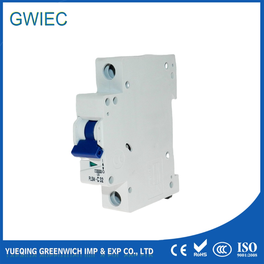
Improper circuit protection presents a serious operational risk on the factory floor. On one side, you face nuisance tripping during routine equipment startup. On the other, you risk catastrophic failure if a breaker cannot clear a fault fast enough. Facility managers and electrical engineers constantly fight this battle. You must balance high inrush current tolerance with strict short-circuit protection requirements. This challenge spans diverse facility loads, including resistive heaters, inductive motors, and highly capacitive lighting arrays.
Time-current characteristic curves provide a standardized method for matching breaker response to specific load profiles. Selecting the correct MCB curve ensures equipment starts reliably while maintaining absolute safety during a short circuit. We will evaluate standard breaker curves and explain exactly how to match them to your electrical loads based on field-tested engineering principles.
Key Takeaways
B Curve MCB (3-5x In): Optimized for resistive loads and general domestic/commercial circuits with minimal inrush current.
C Curve MCB (5-10x In): The industry standard for mixed commercial loads, small motors, and modern lighting arrays with moderate transient surges.
D Curve MCB (10-20x In): Strictly reserved for heavy industrial applications requiring robust motor circuit protection and transformer energization.
Motor Starting Impact: The necessity of a D curve depends heavily on the starting method; Direct-On-Line (DOL) motors require higher magnetic thresholds, whereas VFD-driven motors may safely operate on a C curve.
System Constraints: Upgrading an MCB curve to prevent nuisance tripping requires mandatory verification of Earth Fault Loop Impedance (Zs) to ensure the magnetic trip threshold can still be met during a fault.
Understanding MCB Curve Characteristics and Tripping Physics
Miniature Circuit Breakers rely on a dual-mechanism design to protect electrical circuits. They provide both thermal and magnetic tripping functions. The thermal mechanism utilizes a bimetallic strip to protect against sustained overloads. As current exceeds the rated value, the strip slowly heats up and bends. Eventually, it unlatches the breaker mechanism. This process is intentionally slow. It allows temporary, minor overloads without dropping the power. For example, a conveyor motor might draw slightly more current while pushing an unusually heavy load for a few seconds. The thermal strip absorbs this excess energy without tripping the circuit.
The magnetic tripping mechanism handles short circuits. It uses a precision-wound solenoid coil. When a massive fault current surges through the breaker, the solenoid generates a strong magnetic field. This field pulls a plunger that trips the breaker instantaneously. Instantaneous tripping typically occurs within 0.1 seconds. The specific multiple of the rated current (In) required to trigger this solenoid is what defines the breaker's curve. When the contacts separate during a fault, an electric arc forms. The breaker directs this arc into an arc chute, which splits and cools the plasma to extinguish it safely.
You evaluate these thresholds by reading time-current characteristic graphs provided in manufacturer datasheets. The X-axis represents the current as a multiple of the breaker's rated current. The Y-axis displays the tripping time in seconds. A 10A breaker will have different tripping zones depending on its curve classification. The graph visually separates the slow thermal overload curve from the steep, vertical drop of the magnetic short-circuit response. Engineers use these graphs to verify that the breaker will hold during normal startup but trip before the cable insulation reaches its maximum temperature limit.
Inrush current magnitude and transient duration serve as your primary criteria for selecting the correct curve. When you energize a circuit, certain loads draw a massive spike of current for a fraction of a second. If the breaker's magnetic threshold is too low, this normal startup surge mimics a short circuit. The breaker trips immediately. Understanding the physics of your specific load is the only way to prevent this nuisance tripping. You must measure the peak current and its duration using a power quality analyzer to make an informed selection.
Evaluating the B Curve MCB: General Loads and Resistive Circuits
The B curve MCB features a magnetic trip threshold between 3 and 5 times its rated current. If you install a 20A B curve breaker, the magnetic trip activates when the current hits between 60A and 100A. This tight threshold makes it highly sensitive to sudden current spikes. It leaves very little room for transient surges, which is entirely intentional for specific types of electrical loads.
You should deploy these breakers primarily for resistive loads. Ideal applications include electric heaters, standard incandescent lighting, electric showers, and general-purpose receptacle circuits in residential or light commercial settings. Resistive loads do not generate significant inrush currents. The current they draw upon startup is nearly identical to their continuous running current. A 3kW immersion heater draws about 13A from the moment you switch it on until the thermostat cuts it off. There is no magnetic field to build and no capacitors to charge.
Using this curve provides distinct performance outcomes. It offers the highest sensitivity to short circuits among standard breakers. This rapid fault clearance minimizes thermal stress on standard wiring. It protects thinner gauge cables effectively because the breaker reacts before the wire insulation can overheat during a fault. In older installations with higher loop impedance, the B curve often remains the only safe choice to guarantee a trip under fault conditions. If the wiring is long and thin, the maximum fault current might be quite low, necessitating a highly sensitive breaker.
However, implementation limitations exist. These breakers are highly susceptible to nuisance tripping if you apply them to circuits with moderate capacitive or inductive characteristics. Plugging a large power tool, a vacuum cleaner, or a bank of modern computers into a B curve circuit will frequently cause the breaker to trip upon startup. The initial surge easily exceeds the 3-5x threshold, rendering the breaker unsuitable for mixed commercial loads. Facility managers often waste hours troubleshooting "faulty" equipment when the actual issue is an overly sensitive B curve breaker.
Evaluating the C Curve MCB: Commercial Lighting and Small Inductive Loads
The C curve MCB raises the magnetic trip threshold to between 5 and 10 times the rated current. A 20A version will trip instantaneously when the current reaches between 100A and 200A. This wider tolerance accommodates the transient surges common in modern facilities. It provides a necessary buffer zone that prevents the breaker from dropping the circuit every time a moderate inductive load powers up.
These breakers serve as the industry standard for commercial installations. Ideal applications include commercial fluorescent lighting, IT server racks, small HVAC units, and fractional horsepower motors. They handle the brief inductive spikes created when small magnetic fields energize. When a server rack power distribution unit (PDU) is switched on, the internal power supplies draw a sharp spike of current. The C curve absorbs this spike without interrupting power to critical IT infrastructure.
Managing LED capacitive inrush requires this specific curve. Modern LED lighting relies on electronic drivers. When you flip the switch, these drivers charge their internal capacitors instantly. This creates a massive, microsecond-duration capacitive inrush spike. A single LED fixture might draw 50 times its running current for less than a millisecond. When you gang dozens of fixtures on a single circuit, the combined spike will instantly trip a B curve breaker. The C curve provides the necessary buffer to ride through this startup phase, making it mandatory for modern lighting retrofits.
This curve balances competing needs. It rides through moderate startup transients while maintaining reliable fault clearance for standard commercial cable gauges. You get continuous operation without sacrificing safety. Electrical contractors default to C curves for office fit-outs because they eliminate the callback requests associated with nuisance tripping.
However, you face specific evaluation trade-offs. Because the magnetic threshold is higher, the circuit must be capable of delivering a higher fault current to guarantee instantaneous tripping. This requires a lower earth fault loop impedance (Zs) than a B curve installation. If the cable run is too long, the resistance might prevent the fault current from reaching the 5-10x threshold, delaying the trip and risking a fire. You must verify the Zs values using a loop impedance tester during commissioning to ensure the circuit complies with safety regulations.
Evaluating the D Curve MCB: Heavy Industrial and Motor Circuit Protection
The D curve MCB pushes the magnetic trip threshold to between 10 and 20 times the rated current. A 20A version requires a massive surge of 200A to 400A to trip instantaneously. You strictly reserve this curve for environments where extreme inrush currents are unavoidable. Using a D curve in a standard commercial setting is a severe engineering error that compromises the entire protection scheme.
Ideal applications include large induction motors, heavy welding equipment, X-ray machines, and large low-voltage transformers. These devices require massive amounts of energy to magnetize their cores or overcome physical inertia during startup. A 10kVA transformer can draw an inrush current 15 times its nominal rating when first connected to the supply. An industrial spot welder draws massive current spikes during its duty cycle. The D curve ignores these spikes, allowing the heavy machinery to operate normally.
Your motor starting method directly dictates the curve selection. Direct-On-Line (DOL) motors draw massive locked-rotor amps. When a large DOL motor starts, it acts almost like a short circuit until the rotor gets up to speed. This scenario absolutely requires a D curve for proper motor circuit protection. Conversely, if you use Soft Starters or Variable Frequency Drives (VFDs), the equipment artificially limits the inrush current. In many VFD applications, you can safely step down to a C curve, which provides better overall cable protection.
The primary outcome of using this curve is operational continuity. It prevents costly downtime by allowing massive, short-duration inrush currents without dropping the circuit. Heavy industrial processes rely on this tolerance to function. A manufacturing plant cannot afford to have its main conveyor system trip the breaker every time it starts up under load.
Implementation risks are severe if misapplied. High magnetic trip thresholds mean fault currents must be exceptionally high to trigger the solenoid. This strictly limits your maximum allowable cable lengths. You must have robust, low-impedance grounding systems. If you install a D curve breaker on a long, thin cable run, a short circuit might only generate 8 times the rated current due to cable resistance. The breaker will not trip instantaneously. It will rely on the slow thermal mechanism, potentially melting the cable insulation before the circuit opens.
Specialized Applications: K and Z Curve MCBs
Standard curves do not cover every engineering scenario. Highly specialized industrial environments often require tighter tolerances. Manufacturers produce K and Z curves to address these niche applications where standard B, C, or D curves either fail to protect the equipment or cause unacceptable nuisance tripping.
The K Curve features a magnetic trip threshold of 8 to 12 times the rated current. You use this curve in highly specific motor protection scenarios. Sometimes a D curve is too insensitive, risking cable damage, but a C curve is too prone to nuisance tripping during motor startup. The K curve bridges this gap. It provides a highly calibrated response for specific inductive loads, offering better cable protection than a D curve while still allowing significant inrush. We often see K curves deployed in older manufacturing plants where upgrading the main supply cables to support a D curve is physically impossible due to infrastructure constraints.
The Z Curve operates with a very low magnetic trip threshold of 2 to 3 times the rated current. You apply this curve for ultra-sensitive equipment protection. Applications include semiconductor manufacturing, precision instrumentation, and critical medical equipment. These devices cannot tolerate even minor fault currents. The Z curve ensures the fastest possible fault clearance, sacrificing all inrush tolerance to guarantee absolute protection for delicate electronic components. If a fault occurs on a printed circuit board testing rig, the Z curve breaker clears it before the copper traces vaporize.
Decision Framework: Matching the Load Profile to the Breaker
Selecting the correct breaker requires a systematic engineering approach. You cannot guess based on the equipment type alone. You must match the load profile to the circuit's physical constraints. A mismatch here leads directly to operational failures or safety hazards.
Curve Type
Magnetic Trip Threshold
Primary Load Type
Common Applications
B Curve
3 - 5x In
Resistive
Heaters, incandescent lighting, domestic sockets
C Curve
5 - 10x In
Inductive / Capacitive
LED lighting, small motors, commercial servers
D Curve
10 - 20x In
Highly Inductive
DOL motors, transformers, welding machines
K Curve
8 - 12x In
Specialized Inductive
Specific motor loads requiring tighter protection
Z Curve
2 - 3x In
Highly Sensitive
Semiconductors, medical instrumentation
Your success criteria depend on accurate load profiling. You must calculate or measure the peak inrush current and transient duration of the intended equipment. Consult manufacturer data sheets for this information. Look for the "peak starting current" or "inrush multiplier." Once you know the maximum surge, you select the curve that sits comfortably above that value. Do not rely on generic estimates when dealing with heavy industrial machinery.
Cable sizing and loop impedance (Zs) form the most critical engineering check. You must ensure the prospective fault current at the farthest end of the circuit is high enough to meet the selected curve's magnetic trip threshold. If you select a 20A D curve breaker, your circuit must be capable of delivering at least 400A during a short circuit. You calculate this using the formula: Zs = Ze + (R1 + R2). If the calculated Zs is too high, the fault current will be too low. You must either increase the cable cross-sectional area or select a more sensitive breaker curve.
Selectivity and coordination require careful planning. You must ensure the chosen breaker coordinates properly with upstream molded case breakers or fuses. If a fault occurs on a final circuit, only the local breaker should trip. If your local breaker is too slow, the upstream main breaker might trip first, causing a cascading power outage across the entire facility. Review coordination tables provided by breaker manufacturers to ensure proper discrimination between protective devices.
AC versus DC circuit considerations change the math entirely. Standard breakers are designed for Alternating Current. When you apply them to Direct Current circuits like solar PV arrays or battery storage systems, the magnetic trip thresholds shift. DC arcs are harder to extinguish. You generally must apply a multiplier, typically 1.4x to 1.5x, to calculate the true DC trip threshold of an AC-rated breaker. Always verify if the manufacturer explicitly rates the breaker for DC applications before installation.
Follow these steps when evaluating a new circuit:
Identify the continuous load current to size the breaker's thermal rating.
Determine the peak inrush current from the equipment datasheet.
Select the lowest curve (B, C, or D) that clears the inrush spike.
Calculate the maximum Zs for the selected curve and breaker rating.
Measure the actual circuit Zs to confirm it falls below the maximum allowable limit.
Implementation Risks and Compliance Considerations
Field modifications often introduce severe safety hazards. The most common error is falling into the curve upgrade trap. When a facility manager experiences nuisance tripping on a B curve circuit, the instinct is to simply swap it for a C curve or D curve breaker of the same amperage. This practice is dangerous. Swapping the curve without recalculating the cable current-carrying capacity and loop impedance can create a fire hazard. The existing wiring might not support the higher fault currents required to trip the new, less sensitive breaker. You must treat a curve change as a complete circuit redesign.
Regulatory compliance dictates your selection boundaries. You must align your choices with local electrical codes. In many regions, IEC 60898-1 governs residential and light commercial installations, focusing heavily on B and C curves. Industrial environments typically fall under IEC 60947-2, which provides broader allowances for D and specialized curves. Adhering to these standards ensures your installation passes inspection and maintains insurance validity. Inspectors will flag D curve breakers installed in commercial panels without proper engineering documentation.
Environmental derating impacts breaker performance regardless of the magnetic curve chosen. Breakers are typically calibrated for a specific ambient temperature, often 30°C or 40°C. If you install multiple breakers tightly packed inside a poorly ventilated distribution board, the ambient temperature rises significantly. This excess heat affects the bimetallic strip. The breaker will experience thermal tripping at a lower current than its rated value. You must apply manufacturer derating factors when designing panels for high-temperature environments. For instance, a 20A breaker operating in a 50°C panel might only carry 17A before the thermal mechanism trips.
Conclusion
Audit your existing distribution boards to identify any circuits experiencing frequent nuisance tripping during equipment startup.
Measure the Earth Fault Loop Impedance (Zs) on problematic circuits before authorizing any breaker curve upgrades.
Consult equipment manufacturer datasheets to extract exact inrush current multipliers for all new motor and LED lighting installations.
Update your facility's single-line diagrams to explicitly document the installed breaker curves for future maintenance reference.
FAQ
Q: What is the difference between B, C, and D curve MCBs?
A: The difference lies in their magnetic trip thresholds. B curves trip at 3-5 times the rated current, ideal for resistive domestic loads. C curves trip at 5-10 times the rated current, suited for commercial lighting and small motors. D curves trip at 10-20 times the rated current, reserved for heavy industrial loads with massive inrush currents.
Q: Can I replace a B curve with a C curve MCB to stop nuisance tripping?
A: You cannot do this safely without testing. While a C curve stops nuisance tripping by allowing higher inrush currents, it requires a higher fault current to trip during a short circuit. You must verify the circuit's earth fault loop impedance is low enough to trigger the C curve's magnetic mechanism safely.
Q: Which MCB curve is best for motor circuit protection?
A: A D curve is generally required for large Direct-On-Line (DOL) motors due to their massive locked-rotor starting currents. However, if the motor utilizes a Variable Frequency Drive (VFD) or a soft starter to limit the initial current surge, a C curve is often sufficient and provides better cable protection.
Q: How does inrush current affect MCB curve selection?
A: High initial current draws from inductive or capacitive loads mimic short circuits. If the breaker's magnetic threshold is too low, the inrush current triggers an instantaneous trip. You must select a curve with a threshold high enough to ride through this brief startup surge without dropping the circuit.
Q: What happens if I use a D curve MCB on a standard lighting circuit?
A: The breaker will likely fail to trip fast enough during a short circuit. Because standard lighting circuits often have longer, thinner cables, the resistance limits the maximum fault current. The current may not reach the 10-20x threshold required to trip the D curve instantaneously, potentially causing cable fires.
Q: Are Z curve and K curve MCBs different from standard curves?
A: Yes, they are highly specialized industrial curves. Z curves trip at 2-3 times the rated current, offering ultra-sensitive protection for delicate semiconductor and medical equipment. K curves trip at 8-12 times the rated current, providing precise protection for specific motor and transformer loads where standard curves fail.