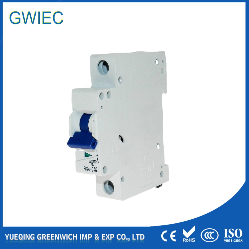
Incorrectly sizing a Miniature Circuit Breaker (MCB) creates an immediate binary risk: nuisance tripping that disrupts critical operations, or thermal overload that degrades conductor insulation and risks catastrophic failure. When you walk onto a job site, you see the results of poor sizing firsthand—melted wire insulation, tripped breakers halting production lines, and panels running dangerously hot. Engineers and facility managers must balance load demands—including transient inrush currents and shared feeder complexities—with strict code compliance (NEC/IEC) regarding conductor ampacity limits. You cannot just look at the nameplate rating of a device and pick a breaker that matches. You must establish a standardized, code-compliant framework for miniature circuit breaker selection that aligns continuous loads, non-continuous loads, and specific application profiles with the correct breaker specifications. This ensures the wiring remains protected under all fault conditions while allowing normal equipment operation without interruption.
The 125% Rule: For continuous loads (operating 3+ hours), the MCB rated current must be at least 125% of the continuous load plus 100% of the non-continuous load to prevent thermal degradation inside the panel.
Conductor Protection is Primary: An MCB is designed to protect the branch circuit wiring, not the end device. The breaker rating must never exceed the lowest ampacity rating of the downstream conductors.
Trip Curves Matter as Much as Amperage: Sizing for inrush currents (like motors or transformers) requires selecting the correct trip curve (Type B, C, or D) rather than simply increasing the base amperage.
Fault Current Verification: MCB breaking capacity must exceed the maximum available short-circuit current at the point of installation to prevent breaker explosion during a dead short.
The Fundamentals of Branch Circuit Protection
A miniature circuit breaker performs two distinct mechanical functions within an electrical panel. It provides thermal protection against prolonged overloads and magnetic protection against instantaneous short circuits. The thermal mechanism relies on a bimetallic strip. When subjected to sustained excess current, this strip heats up, bends, and trips the breaker latch. The magnetic mechanism utilizes a solenoid coil. When a massive fault current surges through the circuit, the solenoid generates a strong magnetic field that pulls the trip latch immediately.
The baseline rule for effective branch circuit protection dictates that the breaker must meet three specific operational criteria. First, it must carry the normal load current indefinitely without overheating. Second, it must tolerate temporary harmless surges, such as motor starting currents, without nuisance tripping. Third, it must interrupt severe fault currents before the downstream conductor insulation melts. Any deviation from these three criteria indicates an improperly sized breaker.
Voltage ratings also play a major role in breaker selection. Alternating Current (AC) and Direct Current (DC) circuits behave differently during a fault. AC voltage naturally crosses zero volts multiple times per second. This zero-crossing helps extinguish the electrical arc formed when the breaker contacts pull apart. DC voltage provides a continuous supply of power, making arc extinction significantly more difficult. You must match the MCB voltage rating to the system voltage. This dictates the breaker's arc-extinguishing capabilities and ensures its true breaking capacity remains valid under fault conditions. Using an AC breaker on a DC circuit often results in the arc sustaining itself across the open contacts, melting the breaker casing.
Electrical codes provide the legal and safety foundation for circuit protection. In North America, NEC Article 210 governs branch circuits. It defines how loads must be calculated and how receptacles should be spaced. NEC Article 240 dictates overcurrent protection, specifically mandating that conductors be protected at their respective ampacities.
Evaluation standards differ globally. North American installations rely heavily on Underwriters Laboratories (UL) standards. UL 489 covers molded-case circuit breakers intended for primary branch circuit protection. These breakers undergo rigorous testing to ensure they can safely interrupt high fault currents. UL 1077 covers supplementary protectors. These devices look identical to UL 489 breakers but are only permitted for use inside equipment where a primary UL 489 breaker or fuse already protects the branch circuit. You cannot use a UL 1077 device as a primary branch breaker.
International installations follow IEC standards. IEC 60898 applies to circuit breakers intended for residential and light commercial use, typically operated by uninstructed personnel. IEC 60947-2 covers industrial circuit breakers, offering higher fault interruption ratings and adjustable trip settings for complex coordination schemes. Engineers designing industrial control panels must also adhere to UL 508A. This standard strictly regulates how components, including miniature breakers, are sized and spaced within the enclosure to manage heat dissipation and fault containment.
How to Size an MCB: The Step-by-Step Calculation Framework
Accurate load calculation forms the foundation of breaker sizing. You cannot size an MCB by guessing or simply looking at the plug on a piece of equipment. Electrical loads fall into two distinct categories based on their operational duration. Continuous loads operate for three hours or more at maximum current. Commercial lighting networks, data center servers, and HVAC ventilation fans typically qualify as continuous loads. Non-continuous loads operate intermittently. General-purpose receptacles, breakroom microwaves, and sump pumps fall into this category.
To determine the baseline requirement, engineers must aggregate all devices on the proposed circuit. The formula node is straightforward: Total Load = (Continuous Load) + (Non-Continuous Load). However, simply adding the amperages together does not yield the final breaker size. The operational nature of the load dictates the next mathematical step.
Heat is the primary enemy of electrical panels. When a breaker carries current continuously, it generates internal heat. If multiple breakers in a densely packed panel operate at their maximum capacity for hours, the ambient temperature inside the enclosure spikes. This ambient heat can prematurely bend the bimetallic strip inside the MCB, causing a thermal trip even if the current has not exceeded the breaker's rating.
To counteract this, the NEC requires engineers to multiply continuous loads by 125% (or divide by 0.8) when sizing the overcurrent device. This ensures the breaker operates at no more than 80% of its capacity during continuous use, leaving thermal headroom.
Consider a commercial lighting circuit drawing a continuous 16 Amps. Applying the multiplier (16A × 1.25) yields 20 Amps. Therefore, the minimum MCB rated current required for this circuit is 20A. If the circuit also included 3 Amps of non-continuous load, the calculation would be (16A × 1.25) + 3A = 23A. Since 23A is not a standard breaker size, you would step up to a standard 25A or 30A breaker, provided the wire is sized accordingly.
The most absolute rule in electrical design is that the circuit breaker exists to protect the wire, not the equipment plugged into it. The relationship between wire gauge (AWG or mm²), conductor temperature ratings (60°C, 75°C, 90°C), and the breaker rating must be strictly maintained.
Conductor sizing must be finalized before selecting the breaker. Engineers must account for voltage drop over long cable runs. They must also apply ambient temperature derating factors if the wires pass through hot environments like boiler rooms or rooftops. If you run four current-carrying conductors in a single conduit on a hot factory roof, NEC Table 310.15(B)(3)(a) requires you to derate the wire ampacity. A wire normally rated for 30 Amps might drop to 20 Amps. You must size the breaker based on this final derated value, not the original 30 Amp rating.
The fundamental rule states that the MCB rating must be less than or equal to the allowable ampacity of the conductor. If a 12 AWG copper wire is rated for 25 Amps at 75°C, the maximum allowable breaker size is 25 Amps. Placing a 30 Amp breaker on a 25 Amp wire creates a severe fire hazard. The wire will overheat and melt its insulation before the breaker recognizes the overload. Exceptions exist primarily for specific motor loads under NEC Article 430, where the breaker handles short circuits while a separate overload relay protects the wire from thermal damage.
Copper Wire Size (AWG)
Typical Ampacity (75°C Column)
Maximum Standard Breaker Size
Common Application
14 AWG
20A (Limited to 15A by NEC 240.4(D))
15 Amps
Residential lighting, standard receptacles.
12 AWG
25A (Limited to 20A by NEC 240.4(D))
20 Amps
Kitchen receptacles, commercial lighting.
10 AWG
35A (Limited to 30A by NEC 240.4(D))
30 Amps
Water heaters, small AC condensers.
8 AWG
50A
50 Amps
Electric ranges, large subpanels.
Evaluating MCB Breaking Capacity and Trip Curves
While the rated current dictates how much normal load the breaker can handle, the Interrupting Rating (IR), or kA rating, dictates how much explosive fault current the breaker can safely survive. When a dead short occurs—such as a hot wire touching a neutral wire with zero resistance—the current spikes massively. This spike is limited only by the size of the upstream utility transformer and the impedance of the wiring.
Engineers must evaluate the available fault current at the specific point of installation. Calculating available fault current requires knowing the transformer kVA rating, its impedance percentage, and the length and size of the wire feeding the panel. A 500kVA transformer with 2% impedance can deliver 25,000 Amps of short-circuit current at its secondary terminals. As you move further away, wire resistance lowers this number. A panel located directly next to a 1500kVA facility transformer might experience short-circuit currents exceeding 40,000 Amps (40kA). A subpanel located 300 feet away might only see 8,000 Amps (8kA) due to the resistance of the long feeder cables.
The MCB breaking capacity must strictly exceed the maximum available short-circuit current. Installing a standard 10kA-rated breaker in a location with 22kA of available fault current guarantees failure. During a short circuit, the breaker will physically explode or weld its contacts closed. It will fail to clear the fault and transfer the explosive energy to the panel enclosure, endangering personnel and equipment.
Amperage ratings only tell half the story. The trip curve determines how the breaker responds to temporary inrush currents. When certain equipment powers on, it draws a massive surge of current for a fraction of a second before settling into its normal running load. Selecting the wrong curve guarantees nuisance tripping.
Type B (3-5x In): These breakers trip instantly when the current reaches 3 to 5 times the rated amperage. They are best suited for resistive loads, domestic applications, and long cable runs where fault levels are naturally low. Typical uses include incandescent lighting and residential receptacle circuits.
Type C (5-10x In): The industry standard for commercial and industrial branch circuits. They tolerate moderate inrush currents, tripping between 5 and 10 times the rated current. They are ideal for fluorescent lighting, small motors, and general industrial loads.
Type D (10-20x In): Required for high inrush loads. These breakers will not trip until the current hits 10 to 20 times the rated amperage. They are mandatory for heavy industrial motors, transformers, welding equipment, and X-ray machines.
There is a distinct trade-off in curve selection. Using a Type D curve on a standard residential circuit risks under-protecting the system against mid-level short circuits. If a fault occurs that only generates 8 times the rated current, a Type D breaker will treat it as a normal motor startup and delay tripping. This delay allows the wiring to overheat and potentially catch fire.
Trip Curve Type
Magnetic Trip Threshold (Multiple of Rated Current)
Typical Application Profile
Primary Risk of Misapplication
Type B
3x to 5x In
Resistive loads, residential lighting, long cable runs.
Nuisance tripping if used on motors or transformers.
Type C
5x to 10x In
Commercial lighting, small motors, standard industrial circuits.
Generally the safest default, but may trip on heavy industrial inrush.
Type D
10x to 20x In
Transformers, heavy motors, welders, high-inrush machinery.
Delayed tripping on low-level faults; risks wire damage if used improperly.
Special Considerations for Motor Branch Circuits
Motors present a unique challenge for circuit protection. An induction motor drawing 10 Amps while running might draw 60 Amps for two seconds during startup. A common, yet dangerous, mistake is artificially increasing the breaker's rated current—for example, installing a 60 Amp breaker on a 10 Amp motor—to prevent startup tripping.
NEC Article 430 provides specific rules for sizing motor branch circuit overcurrent protection. The code recognizes that motors require dual protection. The MCB handles ground faults and short circuits. A separate thermal overload relay, usually integrated into the motor starter, handles continuous slight overloads. Because the overload relay protects the wire from melting during a sustained 15 Amp draw, the NEC allows the short-circuit breaker to be sized much larger than the wire ampacity.
For standard inverse-time circuit breakers, the code often allows the breaker to be sized up to 250% of the motor's Full Load Amps (FLA). This allows the motor to start without nuisance tripping while still providing instantaneous protection if a dead short occurs in the motor windings. If a motor has an FLA of 14A, 250% equals 35A. You can legally install a 35A breaker on 14 AWG wire in this specific motor application, provided the overload relay is sized correctly at 14A.
Industrial panels frequently supply multiple motors from a single shared feeder circuit. Sizing the main breaker for this feeder requires a specific NEC calculation method. You must ensure the breaker can handle the simultaneous running current of all motors, plus the startup inrush of the largest single motor.
The standard calculation requires engineers to size the breaker based on 125% of the largest motor's Full Load Amps (FLA), plus 100% of the FLA of all remaining motors on that branch. If a conveyor system utilizes three motors rated at 20A, 10A, and 10A, the calculation is (20A × 1.25) + 10A + 10A = 45 Amps. The feeder breaker and corresponding conductors must be sized for at least 45 Amps.
Effective miniature circuit breaker selection for motor circuits relies entirely on coordination. The MCB and the thermal overload relay must work in tandem. Thermal overload relays use heater elements or solid-state current transformers to monitor the exact current draw. You set the dial on the overload relay to match the motor nameplate FLA. It will trip if the motor draws 115% of its rated current for an extended period, such as when a conveyor belt jams. If the motor works too hard, the relay opens the control circuit, dropping out the contactor coil and stopping the motor. The MCB remains closed during this process.
The MCB ignores this slight overload, leaving the job to the relay. However, if the motor casing shorts to ground, generating a 500 Amp fault, the thermal relay is too slow to react. The magnetic trip mechanism inside the MCB takes over, clearing the fault in milliseconds before the motor explodes or the wiring catches fire. This highly tuned protection scheme prevents both nuisance downtime and catastrophic failure.
Implementation Risks: Over-Protecting vs. Under-Protecting
Over-protection occurs when a breaker is sized too conservatively or the wrong trip curve is applied. While it sounds safe, it creates severe operational headaches. Common causes include failing to account for ambient temperature derating in hot environments, ignoring the 80% continuous load limit, or mistakenly using a Type B curve for a capacitive load like an LED lighting array.
The operational impact of nuisance tripping is immediate. Unplanned downtime halts production lines. Sudden power loss to server racks causes data corruption. Furthermore, constantly resetting a tripped breaker accelerates mechanical wear on the internal contacts. This wear eventually causes the breaker to fail entirely, requiring a complete panel shutdown for replacement.
Under-protection is a severe safety violation. This occurs when the breaker is sized larger than the wire ampacity, or when the engineer fails to verify the breaker's interrupting rating against the facility's available fault current.
If a 40 Amp breaker is installed on a 20 Amp wire, the equipment can draw 35 Amps continuously. The breaker will never trip, but the wire will heat up, melt its PVC insulation, and ignite surrounding building materials. Similarly, ignoring fault current ratings leads to arc flashes. The impact includes catastrophic fire damage, severe personnel injury, strict code violation fines, and the immediate voiding of commercial insurance policies.
Conclusion
Accurately sizing an MCB requires a holistic view of the entire electrical circuit. It is never merely a matter of matching the breaker amperage to the device's running current on a spec sheet. True protection balances thermal dynamics, magnetic inrush tolerances, and strict adherence to conductor limits. When finalizing your selection, evaluate continuous load calculations, conductor ampacity limits, and the specific inrush profile.
Take the following actions to secure your electrical infrastructure:
Audit all existing branch circuits to verify compliance with the 80% continuous load rule, specifically targeting lighting and server panels.
Calculate the maximum available fault current at every subpanel to ensure no installed breaker is operating below its required interrupting rating.
Standardize trip curve selections across your facility, mandating Type D breakers for transformers and heavy motors while restricting Type B to purely resistive loads.
Review all motor circuits to confirm that short-circuit breakers and thermal overload relays are properly coordinated according to NEC Article 430.
FAQ
Q: What is the 80% rule for sizing an MCB?
A: The 80% rule states that a standard MCB should only be loaded to 80% of its rated current for continuous loads. Continuous loads operate for three hours or more. This prevents thermal tripping caused by heat buildup inside the electrical panel.
Q: How do I choose between a Type B, C, and D MCB?
A: Choose Type B for resistive loads with low inrush, such as residential lighting. Use Type C for general commercial loads and small motors with moderate inrush. Select Type D specifically for high-inrush equipment like heavy industrial motors, welders, and transformers.
Q: Can I use an AC-rated MCB in a DC circuit?
A: Generally, no. AC breakers rely on the voltage crossing zero to extinguish the electrical arc. DC voltage is continuous, making arcs much harder to break. You must use a breaker specifically rated for DC voltage to ensure safe fault interruption.
Q: Why does my MCB trip when a motor starts?
A: Motors draw a massive inrush current during startup, often 6 to 10 times their running current. If your MCB trips on startup, you likely have a Type B or C curve breaker that cannot handle the transient spike. Switching to a Type D curve usually resolves this.
Q: Does the MCB protect the equipment or the wire?
A: The primary function of an MCB is to protect the branch circuit wiring from melting or catching fire. While it provides some secondary protection to the equipment, its sizing is strictly dictated by the ampacity of the conductors in the wall.
Q: What happens if the MCB breaking capacity is too low?
A: If a short circuit generates a fault current higher than the breaker's kA rating, the breaker cannot safely interrupt the flow. The internal contacts may weld together, or the breaker could physically explode, leading to arc flashes and severe panel damage.