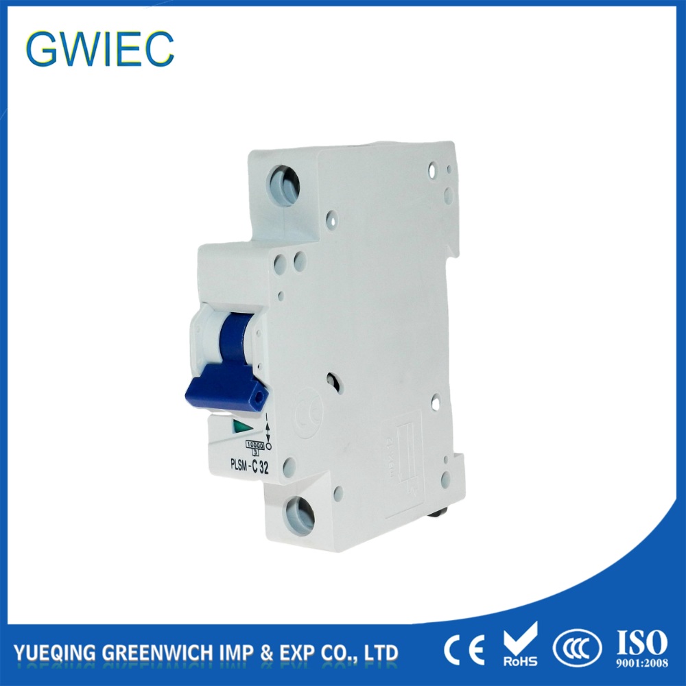
When an MCB trips repeatedly, it signals a severe underlying electrical fault rather than a simple nuisance. Breakers interrupt power flow to prevent catastrophic thermal events, equipment damage, or electrical fires. Resetting a breaker multiple times without diagnosing the root cause exposes your facility to significant operational and safety risks. Continuous downtime disrupts workflow, while compromised wiring poses immediate fire hazards. Ignoring these trips or attempting to bypass the protection mechanism leads to irreversible damage to your electrical infrastructure. We need a systematic, evidence-based approach to isolate the problem. Effective diagnosis requires distinguishing between load issues, failed appliances, wiring faults, and hardware degradation before you make a repair, upgrade, or replacement decision. This guide provides a comprehensive framework to identify exactly why your protection devices intervene and how to resolve the underlying faults safely and permanently.
An MCB that trips repeatedly is rarely a breaker defect; it is a critical symptom of circuit overloads, short circuits, or earth faults requiring immediate isolation.
Effective circuit breaker troubleshooting relies on analyzing trip timing, sequential load testing, and continuity checks rather than arbitrary breaker replacement.
Upgrading an MCB's amperage without upgrading the corresponding branch wiring creates severe fire hazards and violates electrical compliance codes.
Resolving nuisance tripping often requires evaluating the specific tripping curve (Type B, C, or D) against the inrush current characteristics of the connected load.
The Mechanics of Protection: Why MCBs Intervene
Thermal vs. Magnetic Tripping Mechanisms
Miniature circuit breakers utilize two distinct mechanical systems to protect electrical circuits from different types of faults. The thermal protection mechanism relies on a calibrated bimetallic strip. As electrical current flows through the breaker, it generates heat. When the current exceeds the rated limit for a prolonged period, the bimetallic strip heats up and physically bends. This bending action mechanically unlatches the breaker contacts, interrupting the circuit. This delayed action is responsible for MCB overload tripping, allowing temporary, harmless surges while protecting against sustained excessive currents. We see this often when multiple high-draw devices run simultaneously on a single branch. The thermal mechanism acts as a time-delay fuse. It ignores a brief spike from a vacuum cleaner starting up but trips if a space heater runs continuously on an already loaded circuit.
If a panel is located in a boiler room where ambient temperatures exceed 40°C (104°F), the bimetallic strip will bend sooner than it would in a climate-controlled room. You must apply derating factors to the breaker's capacity in these environments to prevent false thermal trips.
Conversely, the magnetic mechanism provides instantaneous short circuit protection. It utilizes a solenoid coil positioned around a movable plunger. During a massive current spike—typical of a short circuit—the sudden rush of electricity induces a powerful magnetic field. This field instantly pulls the plunger, which strikes the latch mechanism and breaks the circuit within milliseconds. This rapid response prevents the massive energy of a short circuit from melting wires or causing an explosion. Inside the breaker, arc chutes safely dissipate the electrical arc generated when the contacts separate under heavy load. Without this magnetic intervention, a dead short would vaporize the copper wiring inside your walls.
Success Criteria for a Healthy Electrical Circuit
A healthy electrical circuit operates within specific, measurable baseline parameters. You cannot expect reliable performance if the system constantly pushes its physical limits. We look for several key indicators when verifying circuit health:
Continuous loads must remain below 80% of the breaker’s maximum rating. This prevents thermal fatigue and premature aging of the bimetallic strip.
Voltage levels must stay stable. Severe voltage drops cause motors to draw more amperage to maintain power, leading to unexpected thermal trips.
Terminal connections at the distribution board and at every receptacle must be torqued to precise manufacturer specifications. Loose connections introduce resistance and heat.
The system must demonstrate an absolute absence of leakage current to ground. All electricity must return through the intended neutral path.
Harmonic currents generated by switching power supplies in office environments must be managed, as they can overheat neutral conductors and cause adjacent breakers to trip.
Primary Root Causes When an MCB Trips Repeatedly
Sustained Circuit Overloads and Failed Appliances
Cumulative amp draw from multiple devices easily exceeds a breaker’s rated capacity, leading to thermal trips. High-draw thermal appliances like space heaters, air conditioning units, or industrial motors operating simultaneously on a single branch circuit are the most common culprits. The breaker functions exactly as designed, preventing the wiring from overheating under the excessive load. Facility managers often encounter this during winter months when employees plug personal heaters into office receptacles sharing a single 20A circuit.
You must distinguish between a general circuit overload and a single failed appliance. A general overload happens when too many healthy devices run at once. A failed appliance draws abnormal current due to internal faults. For example, a motor with failing bearings works harder to turn, drawing higher amperage. A heater with a compromised element might partially short to its casing. Identifying whether the issue is systemic or isolated to one device dictates your next steps.
Short Circuit Faults
A short circuit occurs when a live wire makes direct contact with a neutral wire, bypassing the normal load. This creates a path of near-zero electrical resistance, resulting in a massive and instantaneous current spike. The magnetic coil inside the breaker reacts instantly to clear the fault. These events are violent and generate significant heat.
Visual and olfactory indicators almost always accompany short circuit faults. When inspecting the site, look for scorch marks on wall plates, melted wire insulation inside junction boxes, or blackened terminal screws. You may also notice the distinct smell of ozone or burnt plastic near receptacles. These signs indicate where the massive energy release occurred and dictate where repairs must begin. Rodent damage inside wall cavities frequently causes these hard shorts by stripping the insulation away from parallel conductors.
You must also consider the breaker's breaking capacity, typically rated in kiloamps (e.g., 6kA or 10kA). If the prospective short circuit current exceeds this rating, the breaker contacts can weld shut, failing to clear the fault and causing a catastrophic panel failure.
Earth Faults and Socket-Level Degradation
An earth fault happens when a live conductor touches the earth wire or a grounded metal casing. This creates a dangerous alternative path for electricity to escape the intended circuit. Common localized issues include damaged wiring behind socket faceplates, where wires get pinched during installation, or live-to-earth faults within specific receptacles exposed to moisture or physical damage.
While MCBs handle overcurrent and short circuits, they require massive current to trip during an earth fault. Residual Current Devices (RCDs) or RCBOs specifically monitor for these minute leakage currents. They provide overlapping protection, tripping at much lower thresholds (typically 30mA) to prevent fatal electric shocks when an earth fault occurs. If water leaks into an outdoor junction box, the resulting earth fault will trip the RCD long before the MCB registers an overcurrent condition.
Loose Connections and Localized Heating
Loose terminal screws at the breaker panel or degraded socket contacts create high electrical resistance. Electricity struggles to pass through a poor connection, and this resistance acts exactly like a heating element. The localized heat conducts directly along the copper wire back to the MCB's bimetallic strip.
This external heat source triggers a thermal trip even if the overall circuit load remains well below the breaker's rated capacity. The breaker senses the heat and assumes the circuit is overloaded. Tightening connections using a calibrated torque screwdriver is a mandatory maintenance step that eliminates this hidden cause of frequent tripping.
Legacy installations using aluminum wiring are particularly susceptible to this. Aluminum expands and contracts differently than copper under load, causing terminal screws to loosen over time. This phenomenon, known as cold flow, requires specialized antioxidant compounds and regular re-torquing to prevent localized heating.
Nuisance Tripping and Inrush Currents
Highly inductive or capacitive loads, such as large motors, transformers, or LED lighting drivers, draw massive startup currents for a fraction of a second. This initial surge can easily exceed the breaker's magnetic threshold, causing nuisance tripping. The circuit is entirely healthy, but the breaker misinterprets the startup surge as a short circuit.
This happens when there is a mismatch between the load's inrush current profile and the MCB's designated trip curve. Standard residential breakers are highly sensitive to these spikes. Upgrading the breaker to a less sensitive curve type often resolves this issue without compromising the overall safety of the installation. We frequently see this when retrofitting old fluorescent warehouse lighting with high-efficiency LED high bays; the combined inrush of the LED drivers trips the existing Type B breakers instantly.
Degraded or Defective Breaker Hardware
MCBs have a finite mechanical lifespan. Repeated thermal stress from frequent overloads degrades the internal bimetallic strip, altering its calibration. Harsh environmental conditions, including high ambient humidity, heavy dust accumulation, or corrosive atmospheres, also compromise the internal mechanical linkages and contact points.
Over time, these factors lower the breaker's tripping threshold. A degraded breaker might trip at 10 amps even though its nameplate rates it for 20 amps. When a breaker feels spongy or loose when resetting the toggle, it is a strong indicator that the internal hardware has failed and requires replacement. You can verify this degradation by measuring the actual current draw with a clamp meter; if the breaker trips at 50% of its rated load, the hardware is shot.
Phase 1: Analyzing Trip Timing (Instantaneous vs. Delayed)
Trip timing is your primary diagnostic clue during circuit breaker troubleshooting. You must observe exactly when the breaker trips after being reset. An MCB tripping instantaneously upon reset strongly indicates a dead short circuit or a hard earth fault. The magnetic coil is reacting to a massive, immediate surge of current, meaning the fault is persistent and dangerous.
Conversely, an MCB tripping frequently but not instantaneously—taking minutes or hours to trip—points to gradual thermal buildup. This delayed reaction suggests an overload condition, a failing appliance drawing excess current as it heats up, or a loose connection generating gradual heat. Analyzing this timing immediately narrows down your troubleshooting focus. Do not repeatedly reset an instantaneously tripping breaker; you risk welding the contacts closed.
Phase 2: Safe Isolation and Visual Inspection
Safety protocols are non-negotiable when working with electrical panels. Always de-energize the main breaker before opening the panel cover and utilize appropriate Personal Protective Equipment (PPE). Verify zero energy across all phases using a calibrated multimeter before touching any internal components.
Inspect the panel for loose terminal connections on both the live and neutral bars. Tug gently on the wires to ensure they are seated firmly.
Check for oxidized, pitted, or discolored busbars indicating arcing. Black soot is a clear sign of a loose connection that has been sparking.
Examine wire insulation near the breakers for signs of melting, shrinking, or discoloration. Heat travels up the wire, so melted insulation near the breaker terminal confirms a loose connection or severe overload.
Inspect individual wall sockets on the affected circuit for loose wires or signs of carbon tracking. Remove the faceplates and look for pinched wires.
Look for moisture ingress or dust buildup that could bridge electrical contacts. Clean out any debris using compressed air.
Phase 3: Load Isolation Testing
Unplug all devices and equipment on the affected circuit, then reset the breaker. If the breaker holds without tripping, you have ruled out a hard wiring fault in the walls. Begin sequential load testing by reintroducing loads one by one. Allow sufficient time between each addition for thermal buildup to occur.
This methodical process helps identify whether a specific faulty appliance is causing the trip or if the issue stems from a systemic cumulative overload. If plugging in a specific motor or heater causes the trip, isolate that device for repair. If the trip only occurs when multiple healthy devices run together, you have confirmed a capacity issue. Keep a log of what devices are on the circuit and their respective wattage to calculate the total amp draw.
You can also use a heavy-duty extension cord to temporarily plug a suspected faulty appliance into a completely different circuit. If the new circuit trips, the appliance is definitely the problem. If the new circuit holds, the original circuit is overloaded or has degraded wiring.
Phase 4: Advanced Diagnostic Testing
Use a digital clamp meter to measure the actual current draw under load. Clamp the meter around the live wire at the panel to verify if the circuit is genuinely exceeding its rated capacity. Compare the measured steady-state current and the peak inrush current against the breaker's specifications. Most modern clamp meters have an "inrush" setting specifically designed to capture the millisecond startup spike of motors and compressors.
For hidden issues, perform insulation resistance testing using a Megger. This test applies a high voltage (typically 500V) to the isolated wiring to detect microscopic deterioration in the insulation behind walls or inside conduits. Visual inspections cannot catch these hidden faults, making Megger testing essential for verifying the integrity of aging electrical infrastructure. A reading below 1 Megohm indicates compromised insulation that will eventually cause a dead short.
In addition to Megger testing, use a forward-looking infrared (FLIR) camera to scan the distribution board under full load. A loose neutral connection will glow bright white on the thermal display long before it trips the breaker or melts the insulation.
Evaluating Mitigation Solutions: Repair, Upgrade, or Replace?
Load Redistribution vs. Panel Upgrades
Evaluate the cost and feasibility of moving heavy appliances to different, underutilized circuits. Load redistribution offers an immediate, zero-cost mitigation strategy for overload issues. By balancing the current draw across multiple breakers, you relieve the thermal stress on the tripping MCB without requiring physical modifications to the panel.
In commercial three-phase panels, ensure the load is balanced evenly across L1, L2, and L3. A severely unbalanced panel forces excessive current down the neutral conductor and can cause localized heating that trips adjacent single-phase breakers.
However, if the facility's power demands have permanently increased, load redistribution may not be possible. In these cases, pulling new wire for a dedicated branch circuit becomes necessary. You must weigh the short-term fix of moving equipment against the long-term scalability and safety of executing a comprehensive panel capacity upgrade. Adding a subpanel might be required if the main distribution board lacks physical space for new breakers.
Selecting the Correct MCB Trip Curve
Upgrading from a Type B to a Type C or Type D breaker can resolve nuisance tripping caused by high inrush currents. You must assess the load characteristics carefully. Resistive loads require different handling than highly inductive loads. Ensure the new curve provides adequate short circuit protection without premature tripping during normal equipment startup sequences.
Trip Curve Type
Tripping Current (Multiple of Rated Current)
Typical Applications
Response Time
Type B
3 to 5 times
Residential lighting, standard resistive loads, domestic appliances, long cable runs.
0.04 to 13 seconds
Type C
5 to 10 times
Commercial lighting, small motors, fluorescent lighting, IT equipment, servers.
0.04 to 5 seconds
Type D
10 to 20 times
Heavy industrial motors, large transformers, welding equipment, X-ray machines.
0.04 to 3 seconds
Transitioning to RCBOs or AFDDs
Consider replacing standard MCBs with Residual Current Breaker with Overcurrent (RCBO) or Arc Fault Detection Devices (AFDD). RCBOs combine overload, short circuit, and earth fault protection in one compact unit, saving panel space while drastically improving personnel safety against electric shock. They isolate faults to individual circuits, preventing a single earth fault from taking down the entire main RCD.
AFDDs detect dangerous electrical arcing caused by crushed wires or loose connections that standard breakers completely miss. They analyze the electrical waveform for the specific high-frequency signature of an arc. Evaluate the enhanced fire prevention capabilities against the higher component costs and the potential for increased sensitivity. In environments with aging wiring, wooden structures, or high fire risks, upgrading to these advanced protection devices is a critical safety investment.
Be aware that AFDDs can sometimes experience nuisance tripping when connected to older power tools with brushed motors, as the normal sparking of the carbon brushes mimics a dangerous arc fault. You must evaluate the specific loads on the circuit before installing an AFDD.
Implementation Risks and Compliance Considerations
The Hazard of Arbitrary Breaker Upsizing
Never replace a tripping 15A or 16A breaker with a 20A or 32A breaker without verifying the wire gauge. This is a critical safety violation and a common, dangerous mistake. The circuit breaker exists solely to protect the wire, not the appliance. The wire's cross-sectional area dictates how much current it can safely carry without overheating. For example, a 1.5mm² or 14 AWG wire is rated for 15 amps; putting a 20 amp breaker on it is a recipe for disaster.
If the protection exceeds the conductor's capacity, the wire will overheat during an overload. The insulation will melt, exposing bare copper, and eventually ignite surrounding building materials. Arbitrary upsizing removes the safety net, transforming a tripping nuisance into a severe and imminent fire risk. You are essentially bypassing the safety mechanism entirely.
Regulatory Compliance and Professional Escalation
Local electrical codes, such as the NEC, IEC, or BS 7671, mandate certified electrician intervention for specific panel modifications. Know the limits of in-house maintenance. Basic load testing, visual inspections, and resetting tripped breakers are acceptable tasks for facility managers or homeowners.
However, modifying panel wiring, upgrading breaker sizes, installing new branch circuits, or performing high-voltage Megger testing crosses into territory where liability and safety risks become unacceptable for untrained personnel. Always escalate complex diagnostics to licensed professionals to ensure compliance with safety regulations and to maintain insurance validity. An uncertified modification that results in a fire will void your commercial property insurance instantly.
Conclusion
Map out your circuit loads immediately to identify and relocate high-draw appliances causing thermal overloads.
Torque all accessible terminal screws in your distribution board to manufacturer specifications to eliminate localized heating.
Replace any MCB that feels spongy or trips well below its rated capacity, as the internal bimetallic strip is likely degraded.
Hire a licensed electrician to perform a 500V Megger test if a circuit trips instantaneously and visual inspections reveal no obvious shorts.
FAQ
Q: Why does my MCB trip immediately when turned on?
A: An instantaneous trip usually indicates a dead short circuit or a hard earth fault. This happens when a live wire makes direct contact with a neutral or ground wire, causing a massive current spike. The breaker's magnetic coil reacts instantly to clear the fault. It requires immediate inspection of the wiring and connected appliances to locate the short.
Q: If an MCB trips frequently but not immediately, what does it mean?
A: A delayed trip points to a gradual thermal buildup. This is typically caused by a sustained circuit overload, a failing appliance drawing excess current over time, or a loose terminal connection generating localized heat. The heat transfers to the breaker's thermal mechanism, causing it to trip after minutes or hours of operation.
Q: Can a loose connection cause an MCB to trip?
A: Yes. Loose connections create high electrical resistance, which generates significant heat. This localized heat conducts along the copper wire directly to the breaker's internal bimetallic strip. The breaker senses this external heat and triggers a thermal trip, even if the actual current load is well below the breaker's rating.
Q: How do I know if my MCB is faulty or if there is a real circuit problem?
A: A faulty MCB often has a spongy or loose toggle switch and may trip at loads well below its rating. To verify, use a clamp meter to measure the actual current draw on the live wire. If the current is normal and stable but the breaker still trips, the internal hardware is likely degraded and requires replacement.
Q: What is the difference between MCB overload tripping and a short circuit?
A: Overload tripping is a delayed response caused by too many devices drawing slightly more current than the circuit can handle, which slowly heats the bimetallic strip. A short circuit is an instantaneous, violent response to a massive current spike caused by wires crossing, which immediately triggers the breaker's magnetic coil.
Q: Is it safe to replace a tripping breaker with a larger one?
A: No. Replacing a breaker with a higher amperage rating without upgrading the corresponding wiring is extremely dangerous. The breaker protects the wire. If the breaker allows more current than the wire can safely handle, the wire will overheat, melt its insulation, and potentially cause a severe electrical fire.