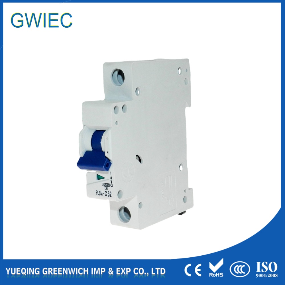
Miniature Circuit Breakers (MCBs) prevent electrical fires, equipment damage, and personnel hazards by isolating circuits during overcurrent or short-circuit events. Specifying the incorrect pole configuration for a distribution board causes severe code violations and wastes enclosure space. It also creates safety hazards like floating neutrals or incomplete phase disconnection during a fault. Selecting between single-pole, double-pole and three-pole MCBs requires strict evaluation of load characteristics, phase requirements, and regulatory compliance. This guide provides a technical framework for specifying the correct MCB configuration. We cover how to match pole counts to system voltages, navigate neutral switching mandates, and eliminate dangerous wiring practices in your electrical infrastructure.
Pole Count Dictates Conductor Isolation: The primary differentiator is the number of independent circuits or phases a breaker simultaneously monitors and disconnects during an overload or short circuit.
Line vs. Neutral Protection: A 1 pole MCB provides single circuit protection (Line only), a 2 pole MCB protects either two Live wires or both Line and Neutral, while 3 pole and 4 pole MCBs are reserved for three-phase industrial applications.
Internal Trip Linkage is Non-Negotiable: True multi-pole breakers utilize an internal common trip mechanism; physically tying the handles of independent single-pole breakers is a severe safety violation for multi-wire circuits.
Neutral Switching Requirements: Deciding between a 3 pole and a 4 pole (or 1P vs. 1P+N) depends entirely on local electrical codes regarding neutral isolation and the presence of unbalanced loads.
Core Mechanics: How Pole Configurations Determine Circuit Protection
Defining the "Pole"
In electrical switchgear, a pole represents a single, independent switching and protection mechanism housed within the breaker casing. Each pole contains its own arc chute, thermal bimetallic strip for overload detection, and magnetic coil for short-circuit interruption. When you select a breaker based on pole count, you dictate exactly how many independent conductors the device will monitor and physically disconnect from the power source. A single pole controls one wire. Multiple poles control multiple wires simultaneously. This physical architecture forms the baseline for all circuit protection strategies. The internal components of a single pole must handle the full fault current of that specific phase without relying on adjacent poles for arc quenching or thermal dissipation.
The Common Trip Mechanism
Multi-pole MCBs are not simply individual breakers glued together. They feature an internal mechanical component known as the common trip bar. This linkage connects the trip mechanisms of every pole inside the housing. If a fault occurs on just one phase of a multi-phase system, the affected pole's bimetallic strip bends or its magnetic coil fires. This action strikes the internal trip latch. The trip latch rotates the common bar, which instantly releases the latches on all other connected poles. This simultaneous disconnection happens within milliseconds. It prevents the partial energization of equipment. Leaving one phase live while others drop out destroys sensitive machinery and leaves maintenance personnel exposed to lethal voltages.
To understand the sequence of a common trip event, consider these mechanical steps:
A short circuit generates a massive current spike on Phase A.
The magnetic coil inside the Phase A pole energizes, pulling the internal plunger.
The plunger strikes the trip latch for Phase A, breaking the contact.
The movement of Phase A's latch rotates the horizontal common trip bar spanning the breaker housing.
The rotating bar physically trips the latches for Phase B and Phase C simultaneously.
All contacts open, and the arc chutes extinguish the resulting electrical arcs across all phases.
Protection vs. Isolation
You must distinguish between a pole that provides thermal-magnetic protection and a pole that merely acts as an isolating switch. A fully protected pole actively monitors the current flowing through it. It trips automatically if the current exceeds safe parameters. An isolating pole, often used for neutral wires, contains no thermal or magnetic trip elements. It relies entirely on the internal trip bar to open when a protected live pole detects a fault. Placing unprotected isolating poles on live conductors leaves the circuit completely vulnerable to overcurrent fires. Always verify the schematic printed on the front of the breaker to confirm which poles contain protection elements.
1 Pole MCB: Specifications and Single-Phase Applications
Technical Characteristics
A 1 pole MCB monitors and interrupts a single ungrounded conductor. It provides thermal-magnetic protection exclusively for that specific live wire. In standard DIN rail enclosures, these breakers occupy a single 18mm module space. They operate by breaking the connection between the supply busbar and the outgoing load wire. The neutral wire bypasses the breaker entirely, terminating directly on the panel's neutral busbar. Installers must torque the terminal screws to the manufacturer's exact specifications, usually between 2.0 and 2.5 Nm, to prevent high-resistance connections that lead to terminal melting.
Standard Applications
You will deploy single-pole breakers primarily in standard 120V or 230V residential and light commercial settings. They serve as the standard choice for basic lighting circuits, general-purpose wall receptacles, and low-draw single-phase equipment. Installers use them to isolate individual rooms or specific lighting zones. Because they only monitor one live wire, they perfectly match the requirements of standard radial circuits where the neutral remains solidly grounded and unbroken at the distribution board. You can easily pack dozens of these 18mm devices into a standard load center, making them highly space-efficient for high-density wiring layouts.
Limitations and Implementation Risks
You cannot use a single-pole breaker for multi-wire branch circuits or heavy 240V appliances. Attempting to protect a 240V load with two separate single-pole breakers creates a severe hazard. If one breaker trips, the other remains closed, leaving the appliance dangerously energized with 120V. While single-pole breakers maximize space efficiency on a DIN rail, you must carefully balance them across the phases in a multi-phase panel. Overloading a single phase with too many single-pole circuits causes severe phase imbalance. This imbalance leads to main breaker nuisance tripping and excessive neutral currents that can overheat the panel's neutral busbar.
2 Pole MCB: Managing 240V Loads and Neutral Switching
Technical Characteristics
A 2 pole MCB occupies two standard slots (36mm total width) on a DIN rail or load center. It monitors two separate conductors simultaneously. The internal common trip mechanism ensures both poles disconnect at exactly the same millisecond during a fault. The breaker physically houses two separate protection mechanisms, or one protection mechanism and one switching mechanism, depending on the specific application requirements. The external toggle handle is physically unified, providing a clear visual indication of the breaker's status across both poles.
Application 1: Two Live Conductors (240V)
In split-phase systems, heavy single-phase loads require two hot wires to achieve 240V operation. You must use a true double-pole breaker for these applications. Common examples include central HVAC compressors, electric water heaters, ranges, and large industrial pumps. The breaker provides thermal-magnetic protection on both live legs. If a short circuit occurs on either leg, the common trip mechanism drops both lines instantly. This completely removes voltage from the appliance. Technicians can then service the equipment safely without the risk of residual voltage traveling through the opposite leg.
Application 2: Line + Neutral (1P+N vs. True 2P)
You must differentiate between a true double-pole breaker and a 1P+N configuration. A true double-pole breaker provides overcurrent protection on both poles. A 1P+N breaker provides protection on the live pole but only acts as a mechanical switch on the neutral pole. Local electrical codes dictate which type you must use. In TT earthing systems, or specific marine and IT network applications, codes mandate complete neutral isolation during a fault. The 1P+N breaker satisfies this requirement by severing the neutral connection alongside the live wire, preventing dangerous feedback loops through the grounding system.
A 3 pole MCB features an architecture designed specifically for three-phase electrical systems. It monitors three separate ungrounded conductors, typically designated as L1, L2, and L3. The breaker occupies three module spaces (54mm) on a DIN rail. Inside, a heavy-duty common trip bar connects all three protection mechanisms. The breaker evaluates the current passing through each phase independently. The tripping action is entirely unified. The device will never open just one or two phases; it is an all-or-nothing protection mechanism designed to keep three-phase systems balanced.
Standard Applications
Commercial and industrial environments rely heavily on three-pole breakers. You will install them to protect three-phase induction motors, large commercial HVAC chillers, and heavy manufacturing machinery. These heavy-duty loads require a balanced supply of power across all three phases to operate correctly. The breaker serves as the primary disconnect and short-circuit protection device at the distribution board, feeding directly to the motor starter or equipment control panel. When wiring these devices, installers must ensure proper phase rotation (L1-L2-L3) to prevent motors from running in reverse.
Phase Imbalance and Motor Protection
The common trip function in a three-pole breaker prevents a catastrophic event known as single-phasing. If one phase experiences a fault or drops out, the motor will attempt to draw the required power from the remaining two phases. This causes a massive current spike in the active windings. Without simultaneous disconnection, the motor windings will overheat and melt within minutes. By forcing all three phases to open the moment one phase faults, the breaker protects expensive industrial machinery from rapid thermal destruction.
When troubleshooting a tripped three-pole breaker on a motor circuit, follow these steps:
Lock out and tag out the breaker at the distribution board.
Use a megohmmeter to test the insulation resistance of the motor windings to ground.
Check for phase-to-phase shorts at the motor peckerhead.
Verify the incoming voltage on the line side of the breaker to ensure the utility supply has not dropped a phase.
Inspect the breaker terminals for signs of thermal damage or loose connections.
4 Pole MCB: When to Switch the Neutral in Three-Phase Systems
3P vs. 4P MCB: The Neutral Conductor Dilemma
The technical distinction between a three-pole and a four-pole breaker centers entirely on the treatment of the neutral conductor. A three-pole setup leaves the neutral hardwired to the distribution board's neutral bus. It only switches the three live phases. A 4 pole MCB routes the neutral conductor through the breaker housing alongside L1, L2, and L3. When the breaker trips, it severs the physical connection to all four wires, completely isolating the downstream circuit from the main power supply. This 72mm wide device provides the highest level of physical isolation available in DIN rail switchgear.
Types of 4 Pole Configurations
You must specify the correct internal configuration when ordering a four-pole breaker. A true 4P breaker provides thermal-magnetic protection on all four poles. You need this when the neutral conductor carries significant current, often due to severe harmonic distortion. A 3P+N breaker provides protection on the three live phases but only acts as a mechanical switch on the neutral pole. The neutral pole in a 3P+N breaker is designed as a late-break, early-make contact. It ensures the neutral disconnects last and reconnects first. This mechanical timing prevents temporary overvoltage conditions that would otherwise destroy single-phase loads connected across the three-phase network.
Compliance and Safety Mandates
Specific infrastructure scenarios legally require four-pole breakers. Facilities utilizing backup generators must often switch the neutral to prevent ground-fault loops between the utility transformer and the generator alternator. High-density IT environments generate massive third-harmonic currents that accumulate on the neutral wire. A true 4P breaker protects the neutral from overheating in these situations. Strict IEC isolation standards in certain jurisdictions mandate complete physical disconnection of all active conductors, including the neutral, before maintenance personnel can legally access industrial control panels.
Evaluation Framework: Selecting the Right MCB for Your Infrastructure
Voltage and Phase Requirements
Selecting the correct pole count starts with a rigid assessment of the load's voltage and phase requirements. You cannot guess or approximate this specification. Use the following matrix to map your load type to the required breaker configuration.
Load Type / Voltage
System Phase
Required Pole Count
Primary Application
120V or 230V
Single-Phase
1 Pole (1P)
Standard lighting, wall receptacles, small appliances.
240V (Split-Phase)
Single-Phase
2 Pole (2P)
HVAC compressors, water heaters, heavy appliances.
230V with Neutral Isolation
Single-Phase
2 Pole (1P+N)
Marine systems, IT racks, TT earthing compliance.
400V or 480V
Three-Phase
3 Pole (3P)
Industrial motors, commercial chillers, heavy machinery.
Modern distribution boards rarely utilize a single breaker type. You must strategically combine different pole configurations to optimize zoned control. A common strategy involves using a heavy four-pole breaker as the main incomer to isolate the entire board. Downstream, you distribute power using three-pole breakers for motor loads and single-pole breakers for individual room lighting. When mixing configurations, you must meticulously balance the single-phase loads across L1, L2, and L3. Failure to balance the panel results in excessive neutral currents and premature tripping of the main breaker. Use a clamp meter during commissioning to verify that the current draw across all three phases remains within a 10% tolerance.
Panel Space and Form Factor Constraints
Physical footprint dictates many design decisions in switchgear retrofits. Standard DIN rail modules measure 18mm in width. A four-pole breaker consumes 72mm of rail space. When enclosure real estate is limited, you must evaluate the trade-offs of different form factors. Compact 1P+N breakers fit into a single 18mm slot, saving massive amounts of space compared to full two-module 2P breakers. These compact devices may have lower short-circuit breaking capacities, typically capping at 6kA instead of 10kA. You must perform careful fault-current calculations before installing compact breakers to ensure they can safely interrupt the maximum prospective short-circuit current at that specific node.
Regulatory Compliance and Local Electrical Codes
Your selection must strictly adhere to local electrical codes. In North America, the National Electrical Code (NEC) dictates specific rules for multi-wire branch circuits, requiring simultaneous disconnection of all ungrounded conductors. In Europe and Asia, IEC standards govern neutral disconnection requirements based on the specific earthing arrangement (TN-C, TN-S, TT, IT). Never finalize a breaker specification without verifying that the pole configuration complies with the exact isolation and protection mandates of your local jurisdiction. Installing a 3P breaker where a 4P is mandated will result in immediate failure during a municipal electrical inspection.
Implementation Risks and Mitigation Strategies
The Handle-Tie Fallacy
One of the most dangerous practices in electrical installation is the handle-tie fallacy. Installers sometimes attempt to create a makeshift multi-pole breaker by physically pinning the plastic handles of two or three independent single-pole breakers together. This is a severe safety violation. External handle ties do not guarantee simultaneous internal tripping under fault conditions. If one phase experiences a massive short circuit, its internal mechanism will trip, but the physical force may not be enough to overcome the mechanical resistance of the adjacent breakers' handles. This leaves the other phases live. You must use factory-assembled multi-pole breakers with an internal common trip bar for all multi-wire circuits.
Miswiring and Floating Neutrals
When installing 1P+N or 3P+N breakers, incorrect wiring leads to catastrophic equipment damage. The neutral pole must operate as a late-break, early-make contact. If miswired, or if a defective breaker causes the neutral pole to open before the live poles, you create a floating neutral condition. In a multi-phase system, a floating neutral instantly subjects single-phase 120V or 230V equipment to full phase-to-phase voltage (up to 400V). This overvoltage instantly destroys power supplies, LED drivers, and sensitive electronics. Always verify the neutral terminal markings (usually labeled 'N') and test the mechanical sequence before energizing the board.
Oversizing and Nuisance Tripping
Pole count alone does not guarantee protection. You must match the breaker's amperage rating and tripping curve to the specific load. Installing a three-pole Type B breaker on a large induction motor will result in constant nuisance tripping during startup due to high inrush currents. Conversely, installing an oversized Type D breaker on a standard lighting circuit removes all effective short-circuit protection, risking a fire before the breaker reacts. Regardless of whether you use a single-pole or four-pole device, the thermal-magnetic characteristics must perfectly align with the conductor gauge and the load's inrush profile.
Trip Curve
Magnetic Trip Threshold
Best Application
Type B
3 to 5 times rated current
Resistive loads, standard lighting, long cable runs.
Type C
5 to 10 times rated current
Inductive loads, small motors, fluorescent lighting.
Type D
10 to 20 times rated current
High inrush loads, transformers, heavy industrial motors.
Conclusion
The choice between single-pole, double-pole, and three-pole breakers is a strict technical requirement dictated by the load's phase configuration, operating voltage, and local neutral switching codes. You cannot substitute pole configurations based on convenience or panel space. Relying on makeshift handle ties or ignoring neutral isolation mandates introduces severe fire risks and code violations into your infrastructure. By understanding the mechanical differences between internal trip bars and late-break neutral contacts, you ensure absolute system reliability and personnel safety.
To implement these standards effectively, execute the following steps:
Audit your existing load schedules to identify the exact phase and voltage requirements for every connected circuit.
Verify the compatibility of your current distribution boards to ensure they have the physical rail space and busbar capacity for multi-pole breakers.
Review your local electrical codes to determine if your specific earthing system requires neutral switching via 1P+N or 4P breakers.
Calculate fault currents and select the appropriate tripping curves (B, C, or D) for your multi-pole devices.
Inspect all existing multi-wire branch circuits and immediately replace any field-installed handle ties with factory-assembled multi-pole breakers.
FAQ
Q: What is the main difference between a 1 pole and 2 pole MCB?
A: A 1 pole MCB protects a single live wire and is used for standard 120V or 230V single-phase circuits. A 2 pole MCB protects two wires simultaneously. It is used for 240V heavy loads requiring two live wires, or for switching both the Line and Neutral conductors simultaneously.
Q: Can I use two 1 pole MCBs instead of a 2 pole MCB?
A: No. This is a severe safety violation and code failure. Independent single-pole breakers lack the internal common trip mechanism required to safely disconnect a multi-wire circuit. If one trips, the other remains live, creating a massive shock and fire hazard.
Q: When should I use a 3 pole MCB?
A: You must use a 3 pole MCB for three-phase electrical systems. They are typically installed in commercial or industrial environments to protect equipment like three-phase induction motors, heavy machinery, and large HVAC chillers from overcurrent and single-phasing.
Q: What is the difference between a 3 pole and 4 pole MCB?
A: A 3 pole MCB handles and protects only the three live phases (L1, L2, L3). A 4 pole MCB handles the three live phases plus the neutral conductor. The 4 pole version physically disconnects the neutral from the circuit when it trips.
Q: Can I mix 1 pole, 2 pole, and 3 pole MCBs in the same distribution board?
A: Yes. Mixed configurations are standard practice for zoned control. You can mix them provided the panel is rated for the total load and you carefully balance the single-phase loads evenly across all three phases to prevent neutral overloading.
Q: What does 1P+N mean on a circuit breaker?
A: 1P+N indicates a breaker that provides thermal-magnetic protection on the live wire while simultaneously acting as a mechanical disconnect switch for the neutral wire. It ensures complete circuit isolation without adding thermal protection components to the neutral path.
Q: Can a 3 pole MCB be used for a single-phase load?
A: While technically possible by wiring poles in series or leaving poles unused, it is highly inefficient and wastes valuable panel space. Furthermore, leaving poles unused may violate the manufacturer's listing instructions and local electrical codes.