Selecting the wrong contactor for a Power Factor Correction (PFC) panel creates severe engineering risks. You risk welded contacts, blown fuses, and catastrophic equipment failure. These failures occur because switching capacitive loads generates massive transient inrush currents. Standard components simply cannot survive this electrical stress. To prevent unplanned downtime, engineers must correctly specify protective components.
This guide breaks down the essential engineering math to help you evaluate your system variables. We will compare choked and unchoked architectures. You will learn step-by-step criteria to specify the right capacitor contactor for industrial applications. Our approach prioritizes safety margins, harmonic awareness, and grid stability. You will discover exactly how to match component ratings to your specific operational voltage and reactive power targets. By the end, you will confidently design robust compensation panels.
Key Takeaways
Standard motor-switching contactors will fail in banked PFC applications; capacitor discharge can generate peak inrush currents exceeding 150 times the nominal current.
Proper sizing requires calculating a minimum continuous current safety margin of 1.43x to 1.5x to account for harmonics and overvoltage tolerances.
System architecture dictates component choice: pure capacitor banks require dedicated capacitor contactors with pre-charge resistors, while systems with detuned reactors shift the sizing focus to heavy-duty contactors and extreme thermal management.
Over-compensating to a Power Factor of 1.0 creates severe resonance risks; targeting 0.9 to 0.95 is the standard engineering best practice.
Standard contactors excel at switching inductive loads like motors. Inductive loads naturally resist sudden changes in current. Capacitors behave in the exact opposite manner. They resist changes in voltage and eagerly absorb massive amounts of current instantly. You must understand this fundamental difference to design reliable electrical panels.
The Inrush Current Reality
When you connect a low-impedance capacitor to the electrical grid, it acts almost like a short circuit for a few milliseconds. The transient inrush current spikes violently. It routinely hits 100 to 200 times the nominal current. A standard switch cannot handle this thermal shock. The intense heat melts the silver alloy contacts. Once the metal cools, the contacts weld completely shut. This creates a dangerous permanent connection.
Individual vs. Banked/Group Compensation
System layout dramatically changes the inrush severity. We divide installations into two main categories.
Individual (Local) PFC: Here, you wire capacitors directly to a specific motor. The long power cables introduce natural electrical impedance. This impedance chokes the initial surge. Peak inrush usually stays below 30 times the nominal current. A high-quality standard contactor might survive this environment.
Banked/Group PFC: Engineers connect multiple capacitors in parallel inside a main distribution board. A depleted capacitor may switch on alongside a fully charged one. The charged capacitor rapidly discharges into the empty one. Inrush routinely exceeds 150 times the nominal current. Standard switches will instantly fail here.
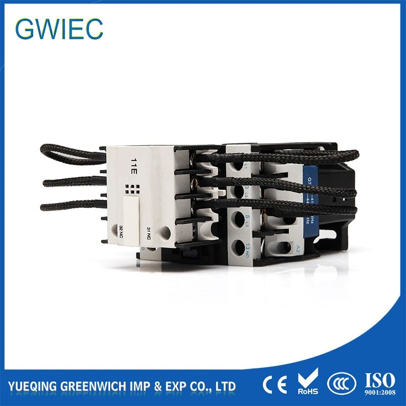
To survive banked environments, you need specialized hardware. Dedicated units feature two vital modifications. First, they use early-make auxiliary contacts. These auxiliary blocks close a fraction of a second before the main power poles. Second, they route the initial surge through damping wire resistors. These pre-charge resistors absorb the worst of the spike. The current drops to a safe level quickly. Then, the main contacts close smoothly. This brilliant mechanical sequence entirely prevents contact welding.
You cannot select components based on guesswork. When browsing industrial catalogs for a capacitor contactor,pfc contactor listings often group these specialized switches together based on specific performance metrics. You must evaluate four critical criteria.
Target Reactive Power (kVAR) & System Voltage
Your foundational baseline involves kVAR and operational voltage. Sizing must strictly align with the specific step kVAR of your panel. Voltage matters heavily. A contactor rated for 50 kVAR at 400V will severely underperform at 480V. Rating curves drop off significantly as voltage increases. Always match your component data sheet directly to your grid voltage.
Peak Switching Capability
Continuous current ratings do not tell the whole story. You must verify the tested limit for peak transient currents. Some budget components boast high continuous ratings but fail under microsecond surges. Check the manufacturer specifications for maximum allowable inrush. The component must confidently absorb 200 times the nominal current without arc degradation.
Harmonic Distortion (THD) and Non-Linear Loads (NLL)
Modern factories run on variable frequency drives (VFDs) and UPS systems. These devices create non-linear loads (NLL). Non-linear loads pollute the grid with harmonic distortion. Capacitors present extremely low impedance to high-frequency harmonics. They eagerly absorb these rogue currents. This harmonic soaking artificially inflates the RMS current passing through your contactor. You must audit your plant load profile before selecting a switch.
Switching Cycle Frequency
How often does your panel switch? Fixed step panels turn on once a day. Automatic step controllers monitor the grid and switch constantly. Dynamic compensation systems switch even faster. High-frequency automatic stepping accelerates mechanical wear. It also prevents the damping resistors from cooling down between cycles. If your panel switches rapidly, you must derate the contactor or specify a heavier duty class.
Follow a rigid mathematical approach to ensure safety and compliance. Guesswork leads to panel fires. Use these four sequential steps to nail down your exact requirements.
Step 1: Calculate Nominal Current
Determine the baseline continuous current flowing to the capacitor step. Use the standard three-phase power formula. Multiply your kVAR by 1000. Divide that number by the square root of 3 (1.732) multiplied by your system voltage.
Step 2: Apply Mandatory Safety Margins
International standards like IEC 60831 demand strict safety buffers. You must apply a multiplier of 1.43x to 1.5x to your baseline nominal current. This buffer absorbs minor grid overvoltage spikes (up to +10%). It also safely handles harmonic overcurrent (up to +30%). Never skip this multiplier.
Step 3: Select the Specific Contactor Class
Take your newly inflated maximum continuous current value. Cross-reference this number with manufacturer capacitor-duty data sheets. Ensure the model supports both your continuous rating and your expected peak inrush limits.
Step 4: Account for Enclosure Temperature
Cramped electrical panels trap heat. Manufacturers test components at a baseline temperature. This is typically 40 degrees or 50 degrees Celsius. If your internal panel temperature exceeds this baseline, you must apply a thermal derating factor. You may need to bump up one size class to compensate for the trapped heat.
Sample Calculation Table
Below is a quick reference table demonstrating the math for common 400V applications using a strict 1.5x safety multiplier.
Step Rating (kVAR) | System Voltage | Nominal Current (In) | Safety Multiplier (1.5x) | Minimum Contactor Rating |
12.5 kVAR | 400V | 18.0 A | x 1.5 | 27.0 A |
25 kVAR | 400V | 36.1 A | x 1.5 | 54.2 A |
50 kVAR | 400V | 72.2 A | x 1.5 | 108.3 A |
Architecture Variables: Choked vs. Unchoked Systems
Your facility environment heavily dictates your panel architecture. You must evaluate the percentage of non-linear loads. This determines whether you build a choked or unchoked panel. Each architecture requires a completely different approach to component sizing and thermal management.
Unchoked Systems (Standard Capacitor Banks)
We install unchoked systems in relatively clean electrical environments. These grids possess fewer variable frequency drives. Non-linear loads make up less than 10% of the total plant capacity. In these setups, capacitors connect directly to the busbars.
You absolutely must use dedicated damping resistor models here. There is no natural impedance to block the inrush surge. Thermally, these panels run quite cool. They typically dissipate roughly 2.5 watts of heat per kVAR. Standard ventilation fans usually handle this thermal load perfectly well.
Choked Systems (Detuned Reactors Added)
Dirty grids demand rugged solutions. When non-linear loads exceed 20%, pure capacitors will fail rapidly. High harmonic environments require detuned reactors. We wire these heavy iron-core reactors in series with the capacitors. They shift the resonance frequency safely away from harmful harmonic orders.
The heavy iron core introduces significant impedance. This natural choke acts as an incredible surge limiter. Because the reactor crushes the initial inrush spike, standard heavy-duty contactors can often safely handle the switching. However, you face a new problem: extreme heat.
A choked system dissipates massive thermal energy. Heat output skyrockets to roughly 9 watts per kVAR. Panel builders must drastically upsize their ventilation systems. A common engineering rule states you must calculate required airflow using a strict formula. Multiply your total dissipated watts by 0.3. This gives you the required cubic meters per hour of cooling. Without this aggressive ventilation, the ambient heat will degrade both your capacitors and your switches.
Architecture Comparison Chart
Review this HTML chart summarizing the core differences between the two panel designs.
Feature | Unchoked System | Choked System |
Application Environment | Clean grids (NLL < 10%) | High harmonic grids (NLL > 20%) |
Inrush Protection | Relies on switch pre-charge resistors | Relies on series detuned reactor |
Switch Type Required | Dedicated damping resistor models | Standard heavy-duty models (oversized for RMS) |
Thermal Dissipation | Low (~2.5W / kVAR) | Extremely High (~9.0W / kVAR) |
Ventilation Needs | Standard louvers or small exhaust | High-CFM forced air extraction |
Common Sizing Mistakes and Avoidable Risks
Even seasoned engineers occasionally stumble when designing PFC panels. A minor oversight cascades into a dangerous failure. You must proactively avoid these three common pitfalls.
The "Power Factor = 1" Myth
Many plant managers mistakenly believe they should target a perfect 1.0 Power Factor. They instruct engineers to size the steps to achieve unity. This creates a severe operational hazard. A perfect 1.0 Power Factor creates a parallel resonance circuit between the facility and the utility grid. When a major machine powers off, this resonant circuit generates destructive high voltages. These voltage spikes increase arcing stress on the switch poles. They also blow fuses and shred capacitor dielectrics. The industry standard dictates targeting a conservative 0.9 to 0.95 lagging.
Ignoring Thermal Derating in Grouped Steps
Space costs money inside electrical cubicles. Builders often pack multiple switches tightly side-by-side on a single DIN rail. This density creates localized heat pockets. An unventilated cluster severely degrades the current-carrying capacity of the middle switches. The central units cannot shed heat. Their internal thermal overload trips prematurely. Always leave adequate spacing between components and strictly follow the manufacturer derating curves for ambient temperature.
Sometimes you size the switch perfectly but ruin the panel by choosing the wrong circuit breaker. Engineers often select a Molded Case Circuit Breaker (MCCB) based purely on the nominal current. When the panel cycles on, the massive inrush surge trips the undersized breaker instantly. This causes nuisance tripping. You must size your breakers and fuses to coordinate cleanly with the 1.5x safety margin of your switch gear. Mismatched coordination frustrates maintenance crews and destroys automated efficiency.
Conclusion
Specifying industrial panel components demands rigorous attention to physics and math. You must carefully calculate your nominal current and apply the unyielding 1.5x continuous current safety margin. Do not compromise on pre-charge resistor technology for unchoked systems. You need those auxiliary blocks to absorb the devastating initial spikes.
Focusing on high-quality component selection directly protects your facility. The slight premium for a properly specified, manufacturer-validated switch prevents unplanned facility downtime. It guards your infrastructure against disastrous fires and saves you from purchasing expensive replacement capacitors every few months. Reliable components keep your production lines running smoothly.
Your immediate next step involves a plant audit. Assess your facility harmonic profile today. Measure your total harmonic distortion for current (THDi) and voltage (THDv). Once you definitively know your harmonic load, you can safely decide between a standard capacitor bank or a heavy-duty detuned reactor setup. Make the math drive your purchasing decisions.
FAQ
A: A standard unit only has main power poles designed for inductive loads. A specialized capacitor unit features early-make auxiliary contact blocks wired with damping resistors. These auxiliary contacts close milliseconds before the main poles. The resistors absorb the massive initial capacitive inrush surge, preventing the main silver contacts from welding together.
A: Standard engineering practice and IEC compliance dictate a strict 1.43x to 1.5x multiplier on the calculated nominal current. This robust margin allows the switch to safely handle continuous harmonic overcurrents and unexpected grid voltage fluctuations without overheating or failing prematurely.
Q: Can I use a VFD to correct power factor instead of a capacitor bank?
A: Variable Frequency Drives (VFDs) naturally correct displacement power factor because they convert incoming AC to DC. However, VFDs cause severe distortion power factor by injecting harmonic noise back into the grid. Your overall power quality strategy depends entirely on balancing these distinct load types.


