Electrical networks power modern industry. However, they carry immense risks when faults occur. Unchecked surges can melt wiring, destroy sensitive machinery, or trigger catastrophic fires in seconds. Selecting the right moulded case circuit breaker requires balancing strict safety compliance, panel space constraints, and tight budgets. For facility managers and electrical engineers, under-specifying risks catastrophic failure and serious code violations. Conversely, over-specifying wastes valuable enclosure space and ties up unnecessary capital.
This guide deconstructs the primary technical parameters you must evaluate. We will explore frame size limits, breaking capacities, and modern trip unit technologies. You will gain a pragmatic framework to specify components for industrial and high-capacity commercial panels confidently.
Key Takeaways
Frame Size vs. Rated Current: A breaker’s frame size (e.g., 250A) dictates its physical footprint and maximum capacity, but the rated current (e.g., 160A) defines its actual operational threshold. Upsizing the frame improves heat dissipation and allows for future scalability.
Ics Must Match Criticality: While Icu denotes the absolute maximum fault a breaker can clear once, Ics indicates the fault level it can clear while remaining operational. Mission-critical facilities should specify MCCBs where Ics = 100% Icu.
Trip Unit Trade-offs: Thermal-magnetic units offer cost-effective, robust protection for standard loads, whereas electronic trip units provide granular adjustability (down to 0.4In) and superior performance in high-temperature environments.
Environmental Derating is Non-Negotiable: Baseline specifications assume standard conditions. Operating above 50°C or at altitudes exceeding 2,000 meters requires strict capacity derating.
The Baseline Specifications: Rated Current (In) vs. Frame Size (AF)
Engineers often confuse rated current with frame size. Clarifying this distinction helps you optimize panel design and ensure future scalability. These two parameters dictate both operational boundaries and physical constraints.
Defining Rated Current (In)
Rated current defines the continuous load a breaker handles without tripping. Manufacturers calibrate this value at a specific ambient temperature. If you exceed this current continuously, the breaker will open the circuit to prevent overheating.
A reliable engineering rule of thumb exists here. Always calculate your total continuous load first. Then, add a 20-25% safety margin. This margin prevents nuisance tripping under standard conditions. For example, if your calculated load reaches 125A, specify a 160A rated current. This buffer accommodates minor load fluctuations.
Understanding Frame Size (AF)
Frame size represents the physical housing. It also defines the internal switch mechanism's maximum current capacity. Think of it as the absolute limit of the breaker's chassis. A larger frame utilizes heavier internal contacts and more robust arc chutes.
Industry standards generally divide frame sizes into three core categories:
Small Frame (16A–250A): Commonly deployed for branch circuits, small motor protection, and localized control panels.
Medium Frame (250A–630A): Ideal for secondary distribution boards and mid-sized industrial machinery.
Large Frame (630A–1600A): Reserved for main feeders, heavy industrial mainlines, and massive switchgear setups.
The "Underrated" Frame Strategy
Savvy designers frequently employ an underrated frame strategy. They specify a lower rated current on a significantly larger frame. You might install a 160A trip unit inside a 250A frame. This approach delivers compelling business outcomes.
First, it provides superior thermal stability. The larger chassis offers enhanced heat dissipation. Second, it allows seamless future capacity upgrades. If facility loads increase later, you can simply adjust or swap the trip unit. You avoid replacing the entire breaker physically. You also skip redesigning the busbars or panel layout.
Parameter | Definition | Primary Function |
Rated Current (In) | Continuous current limit at standard temp. | Dictates the normal operational threshold. |
Frame Size (AF) | Maximum physical capacity of the housing. | Defines spatial footprint and upgrade limits. |
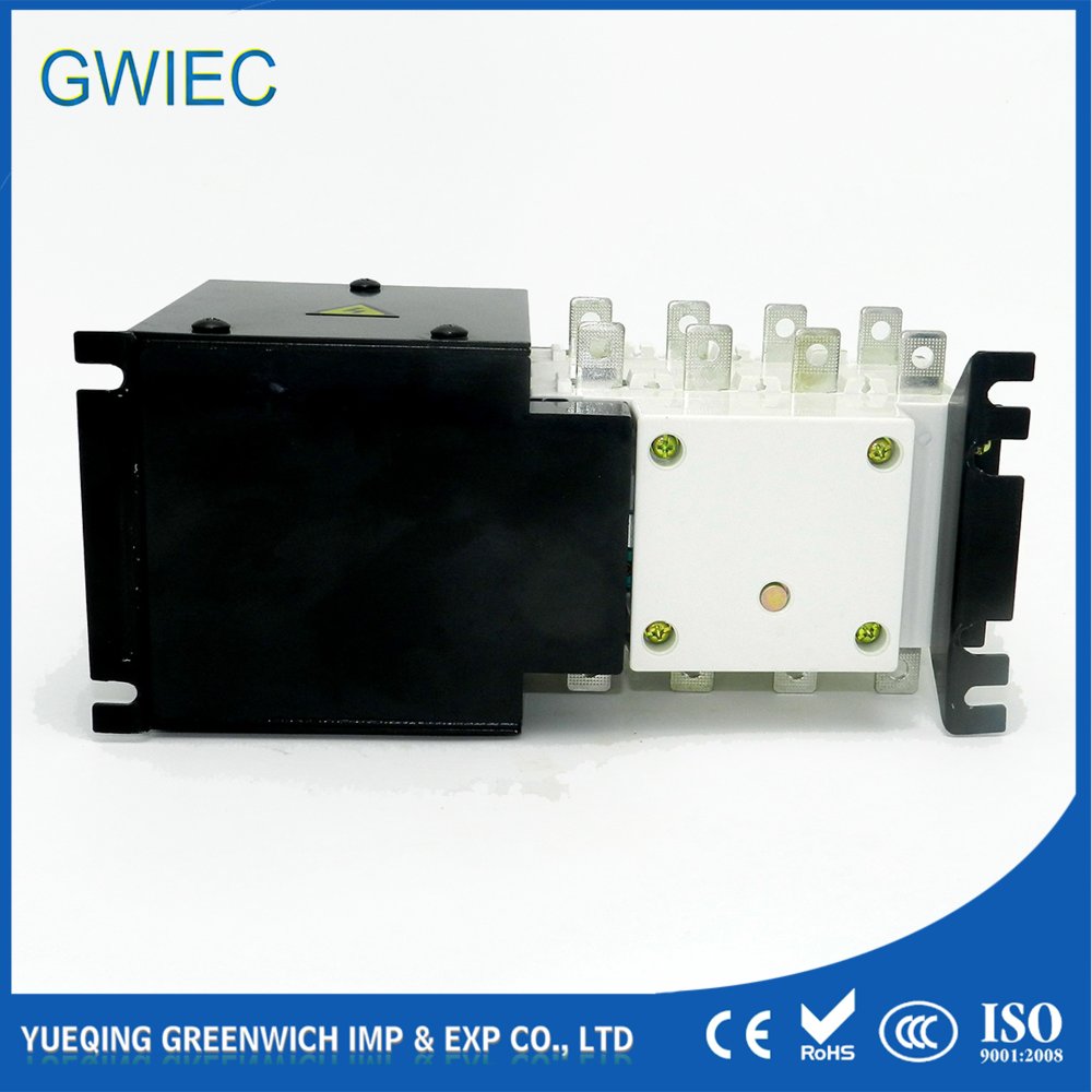
Deciphering Breaking Capacity (Icu vs. Ics) and Fault Levels
Evaluating short-circuit protection thresholds requires careful analysis. You must understand Prospective Short-Circuit Current (PSCC) and your specific facility risk profile. Failing to align these factors invites catastrophic electrical fires.
Calculating Prospective Short Circuit Current (PSCC)
PSCC forms the absolute foundation of breaking capacity selection. You can calculate it using a standard formula: PSCC = V / Z_total. Here, V represents voltage, and Z_total represents total circuit impedance. The breaker's breaking capacity must exceed this theoretical maximum fault at the exact installation point. If a fault exceeds the breaker's capacity, the internal contacts may weld together.
Ultimate Short-Circuit Breaking Capacity (Icu)
Icu indicates the absolute maximum fault current a breaker can successfully interrupt exactly once. Manufacturers verify this using an O-t-CO test sequence (Open - time delay - Close/Open). During an Icu-level event, the breaker stops the fault. However, the extreme thermal and mechanical stress often damages the internal components. Following such an event, you will likely need to replace the entire unit. It serves as your last line of defense.
Service Short-Circuit Breaking Capacity (Ics)
Ics paints a more practical picture. Manufacturers express it as a percentage of Icu. You will typically see values of 25%, 50%, 75%, or 100%. Ics indicates the fault level the breaker can clear multiple times while remaining fully operational. If a fault hits the Ics threshold, the breaker safely clears it. You can simply reset the toggle and resume operations.
Evaluation Criteria
Your application determines the required Ics percentage. Standard commercial applications often tolerate Ics = 50% Icu. If a rare major fault occurs, maintenance teams can afford the time to replace the breaker.
Heavy industrial plants, data centers, and healthcare facilities face different realities. Downtime remains strictly unacceptable. In these environments, specifying an MCCB with Ics = 100% Icu represents standard risk-mitigation practice. It ensures the infrastructure survives major electrical shocks and bounces back immediately.
Trip Unit Technologies: Thermal-Magnetic vs. Electronic
The trip mechanism acts as the brain of the breaker. Guiding the buyer toward the right trip unit requires evaluating specific load types, precision needs, and budget constraints. Two dominant technologies rule the market.
Thermal-Magnetic Trip Units (TM)
Thermal-magnetic units rely on traditional, robust mechanics. For overload conditions, they use a bimetallic strip. As current increases, heat causes the strip to bend. Eventually, it trips the mechanism. For short circuits, they utilize an electromagnet. A massive current spike generates a strong magnetic field, pulling the armature and tripping the breaker instantly.
Pros: They are highly robust and highly cost-effective. They serve general-purpose distribution exceptionally well.
Cons: They suffer from limited adjustability. You typically find adjustment ranges restricted to 0.7–1.0x In. Furthermore, the bimetallic strip remains sensitive to ambient temperature fluctuations.
Electronic / Microprocessor Trip Units
Electronic units discard traditional mechanics for modern silicon. They use current transformers and built-in microprocessors to evaluate current flows constantly. They analyze the waveform and trigger the trip mechanism based on programmed logic.
Pros: They deliver extreme precision. You gain high adjustability, often dropping down to 0.4–1.0x In for overload settings. They also boast superior high-temperature tolerance. They easily maintain accuracy in environments reaching 60-70°C.
Cons: They demand a significantly higher upfront cost compared to traditional units.
Matching Trip Curves to the Load
You must match the trip curve precisely to the load characteristics. Nuisance tripping happens when engineers ignore inrush currents.
Curve Type | Trip Threshold | Ideal Application |
Type B | 3–5x In | Resistive loads. Perfect for heaters and standard lighting. |
Type C | 5–10x In | Inductive loads. Ideal for small motors and fluorescent lighting. |
Type D / K | 10–20x In | High inrush loads. Crucial for heavy industrial motors and transformers. |
Type Z | 2–3x In | Highly sensitive solid-state electronic equipment. |
Operational Realities: Derating, Environment, and Accessory Integration
Theoretical specifications often fail when confronted with real-world environments. Addressing practical implementation factors prevents premature failures. Environmental stress and physical panel limits play massive roles in successful deployments.
Temperature & Altitude Derating
Baseline ratings assume standard conditions. Standard specifications usually anchor to an ambient temperature of 40°C. If your panel sits in a sweltering industrial boiler room reaching 50°C, you must apply a derating coefficient. Usually, you multiply the rated current by 0.9. At 60°C, that factor drops to 0.8x In. Ignoring this guarantees thermal nuisance tripping.
Altitude also penalizes electrical equipment. Installations climbing above 2,000 meters face severe challenges. Thinner air significantly reduces natural cooling efficiency. It also degrades the air's dielectric strength. You must implement strict voltage and current derating rules to prevent internal arcing.
Physical Constraints & Cable Sizing
Before purchasing, vigorously verify the physical dimensions. Check the Width, Height, and Depth (W/H/D) against your panel constraints. Confirm whether you need fixed, plug-in, or withdrawable configurations. Space runs out quickly in crowded enclosures.
Terminal compatibility remains equally critical. Ensure terminal sizes match your required cable cross-sections. For instance, standard 160A applications typically demand 70–95 mm² copper cabling. This requirement depends heavily on local building codes and routing methods. If the lugs cannot accept the cable, your installation stalls.
Specifying Essential Accessories
When specifying a moulded case circuit breaker,MCCB accessories provide vital integration capabilities. Basic standalone protection rarely satisfies modern industrial demands. You need to tie the breaker into broader facility safety networks.
Shunt Trips & Undervoltage Releases (UVT): These represent critical safety add-ons. They allow remote tripping and facilitate emergency shutdown protocols. Engineers frequently use them to integrate panels with facility fire alarm systems.
Auxiliary Contacts: These tiny additions feed status information back to central computers. They prove essential for status monitoring in SCADA or sophisticated Building Management Systems (BMS).
The 5-Step Evaluation Checklist for Specifying an MCCB
Finalizing a procurement decision requires a methodical approach. Skipping steps leads to costly redesigns. Use this concise, actionable workflow to specify the correct protective device every time.
Map the Continuous Load: Start with the raw math. Calculate the total current using the formula I = P ÷ (V × PF). Once you have the base current, apply a strict 1.25x safety margin. This result determines your required Rated Current (In).
Determine the Fault Level: Gather impedance data from the utility transformer down to your panel. Calculate the site PSCC. This theoretical maximum fault defines the absolute minimum Icu rating you can safely deploy.
Define System Criticality: Evaluate the cost of downtime. Select your Ics percentage based on required post-fault uptime. For hospitals, data centers, and critical infrastructure, always aim for an Ics rating that equals 100% of Icu.
Select the Trip Unit & Curve: Choose between Thermal-Magnetic mechanisms for standard economics or Electronic units for high precision and high-temperature environments. Next, match the operational curve (B, C, or D) to your load's specific inrush characteristics.
Verify Compliance & Environment: Demand proper certifications. Confirm the unit passes IEC 60947-2 testing. Apply all necessary derating factors for local temperature peaks and installation altitude. Finally, verify enclosure space dimensions and accessory compatibility.
Conclusion
Selecting reliable protection components extends far beyond merely matching nominal amperage to a basic load. It demands a rigorous evaluation of your facility’s fault current potential, environmental stressors, and required system uptime. Standard off-the-shelf picks often fail when applied blindly to heavy industrial realities.
Start by prioritizing appropriate frame sizing to guarantee future scalability. Next, deliberately match Ics ratings to your site's specific mission criticality. Always account for environmental derating rules mathematically before finalizing the bill of materials. By carefully applying these principles, specifying engineers will ensure robust facility protection and maintain strict electrical code compliance.
FAQ
Q: What is the practical difference between an MCB and an MCCB?
A: Miniature Circuit Breakers (MCBs) handle smaller loads. They are typically limited to 125A with short-circuit capacities under 15kA. They suit residential or light commercial settings. MCCBs process heavy loads. They handle up to 1600A+ with breaking capacities exceeding 100kA. Engineers design them specifically for industrial and heavy-duty power distribution.
Q: Can I use an AC-rated MCCB for a DC solar/battery application?
A: Not generally. DC arcs burn intensely and prove significantly harder to extinguish. They lack the natural "zero-crossing" point found in alternating AC currents. You must explicitly specify a dedicated DC-rated breaker. Manufacturers engineer these specific models with specialized arc chutes to handle continuous direct current safely.
Q: Why does my MCCB trip before reaching its rated current?
A: Ambient panel temperatures usually cause this phenomenon. Standard breakers calibrate to a baseline of 40°C. If internal enclosure heat exceeds this mark, the bimetallic strip bends prematurely, causing thermal nuisance tripping. To resolve it, improve panel ventilation or apply manufacturer derating tables to select a higher rated current.


