Connecting high-capacitance loads to an active power source triggers a surprisingly volatile event. For a fraction of a second, these completely discharged components act almost exactly like a direct short circuit. Unmanaged inrush currents constantly threaten the core integrity of the entire electrical assembly. They cause immediate contact welding, induce severe grid voltage sags, and drastically accelerate premature component failure. Left unchecked, this intense thermal and electrical stress creates massive hazards for modern infrastructure. You will soon discover how specialized pre-charge resistors seamlessly integrate into a purpose-built capacitor contactor to mitigate these severe operational risks. We will explore the specialized two-stage switching mechanics driving these safety devices. Furthermore, we will thoroughly detail proper specification criteria and examine common design pitfalls. Ultimately, you will learn how applying the correct hardware actively extends equipment lifespan and ensures total system stability across demanding electrical applications.
Key Takeaways
Unmitigated inrush currents in capacitive circuits can exceed nominal currents by 20 to 100 times, causing immediate hardware degradation.
A capacitor contactor utilizes a specialized two-stage switching mechanism with pre-charge resistors to safely buffer the initial power surge.
Proper evaluation requires matching the resistor’s thermal mass and ohmic value to the system’s capacitance, voltage, and required pre-charge time.
Specifying the right pre-charge circuit prevents catastrophic failure in high-demand applications like EVs, solar/ESS inverters, and industrial AC drives.
The Engineering Problem: Unmanaged Inrush Current
The Physics of Capacitive Loads
A capacitor stores electrical energy inside an electrostatic field. When completely discharged, its internal voltage potential sits at zero. You connect it directly to an active power line. Electrons rush into the component instantly. Ohm's law strictly dictates this aggressive current spike. Because the internal resistance remains negligible, the circuit pulls maximum amperage. Engineers call this sudden surge the inrush current. It often exceeds normal operating levels by staggering margins. The system remains in a near-short-circuit state until the dielectric field stabilizes.
Hardware Consequences
The physical toll on your switching hardware is massive. Standard switches cannot possibly absorb this sudden thermal shock. The rushing electrons create intense localized heating across the metal surfaces. Contact asperities melt instantly under the load. We refer to this common damage as contact pitting. High-amperage plasma arcs frequently form between the separating gaps. These arcs generate extreme heat. The metal surfaces eventually fuse together into a permanent micro-weld. This catastrophic failure renders the switch entirely useless.
System-Level Impact
Beyond the single device, system-wide network failures frequently occur. Upstream circuit breakers misinterpret the sudden surge as a genuine short circuit. They trip unexpectedly. We call this frustrating phenomenon nuisance tripping. The sudden power draw also drops the local grid voltage. Neighboring sensitive equipment suffers from these voltage disturbances. They might reset, reboot, or shut down completely. Your facility consequently faces highly expensive, unplanned maintenance downtime. You must dispatch technicians to identify and replace the fused components.
Success Criteria for Mitigation
We need a comprehensive engineering solution. A highly successful mitigation strategy must strictly satisfy several non-negotiable operational requirements:
Controlled peak current: The system must cap the initial surge tightly below any destructive thermal thresholds.
Robust thermal stability: The dampening components must absorb immense heat rapidly without suffering internal physical degradation.
Seamless power transition: The shift from the buffering phase to continuous main power delivery must occur smoothly.
The Two-Stage Switching Mechanism
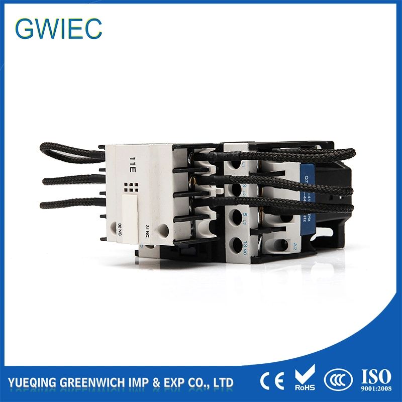
A purpose-built capacitor contactor efficiently prevents this systemic destruction. It operates using a highly choreographed two-stage switching sequence. This protects the entire electrical assembly.
Stage 1 (Pre-Charge)
Early-make auxiliary contacts act first. They close deliberately before the main circuit path. They force the incoming electrical flow exclusively through a pre-charge resistor block. This component safely buffers the sudden surge. The capacitor steadily charges up to about 80% to 95% of its total capacity. The voltage climbs smoothly.
Stage 2 (Main Connection)
The main contacts engage just milliseconds later. They firmly bypass the resistor block entirely. Because the capacitor now holds a substantial charge, the voltage differential drops significantly. The main contacts easily carry the continuous nominal current. They experience zero arcing or thermal shock.
Inrush Current Control
Think of the resistor as a strict mechanical bottleneck. It actively flattens the violent current spike. It transforms a dangerous vertical surge into a smooth, manageable curve. The component acts essentially as a shock absorber for the electrical grid. It safely dissipates a portion of the surge energy as manageable heat. This elegant control mechanism fundamentally protects the delicate dielectric layers inside your capacitors.
Standard AC-3 contactors lack this essential staging capability. They bridge the connection instantly across a single pathway. Improvised setups using standard switches constantly fail under repeated stress. They lack the precise mechanical timing found in specialized equipment. Purpose-built devices offer proven, integrated protection. They safely handle the punishing dynamics of modern high-capacitance loads. Relying on standard contactors guarantees an unacceptably high failure rate.
Evaluation Criteria: Specifying the Right Pre-Charge Circuit
Calculating the RC Time Constant
You must carefully specify the correct pre-charge circuit parameters. Calculation always begins by finding the RC time constant. You multiply the target resistance by the total system capacitance. This mathematical product defines how quickly the system accepts charge. Industry guidelines typically suggest maintaining the pre-charge state for three to five time constants. This specific duration allows the internal voltage to reach safe operational levels.
| | RC Time Constant (τ) Charge Curve Data Chart |
Time Constant Duration | Capacitor Voltage Reached (%) | Remaining Inrush Potential (%) |
1τ (R × C) | 63.2% | 36.8% |
2τ | 86.5% | 13.5% |
3τ | 95.0% | 5.0% |
4τ | 98.2% | 1.8% |
5τ | 99.3% | 0.7% |
Thermal Capacity and Joule Ratings
Next, evaluate the raw thermal capacity. Resistors absorb massive energy spikes during the brief charge cycle. We precisely measure this absorbed energy in Joules. The component must handle this intense, rapid heat influx safely. It must not exceed its critical thermal limits. If the Joule rating falls short, the internal resistive element simply vaporizes. You must calculate the exact kinetic energy transfer accurately.
Voltage and Environmental Constraints
Consider your maximum system voltage carefully. Modern electrical architectures frequently push 800V limits. Higher voltage levels demand significantly robust dielectric insulation. Ambient operating temperatures also heavily impact resistor performance. Hot industrial environments require strict thermal derating calculations. You must adjust your final specifications accordingly. A resistor performs differently at freezing temperatures versus a sweltering factory floor.
Finally, review your physical form factor choices. You basically face two distinct integration paths. Discrete setups utilize separate relays alongside massive external resistors. They consume highly valuable panel space. They also introduce complex, error-prone wiring schematics. Integrated designs house the required resistor blocks directly within the contactor body. They save considerable space. They drastically simplify your overall wiring logic.
Feature Category | Standard AC-3 Contactor Setup | Integrated Capacitor Contactor |
Mechanical Staging | Single-stage simultaneous closure. | Two-stage sequential closure mechanism. |
Surge Protection | None. Absorbs full inrush spike. | Built-in dampening via resistive block. |
Panel Footprint | Requires extra discrete components. | Compact, all-in-one housing design. |
Failure Probability | High risk of contact micro-welding. | Extremely low risk under normal duty. |
High-Stakes Application Environments
Electric Vehicles (EV) and DC Fast Charging
High-stakes engineering environments demand utterly flawless execution. Electric vehicles heavily rely on these protective circuits. DC fast chargers routinely connect massive high-voltage battery packs to vehicle motor controllers. The internal bus capacitors demand careful energy management. An unmitigated connection easily destroys standard relays. Implementing a robust capacitor contactor permanently prevents this internal relay destruction. It ensures safe daily vehicle operation.
Solar Storage and Inverters
Solar energy storage systems behave remarkably similarly. Modern inverters contain exceptionally large DC bus capacitors. Startup sequences send tremendous power rushing directly into these delicate components. Unmanaged surges frequently trip the intelligent Battery Management System. This falsely triggers internal safety fault codes. Careful, staged pre-charging guarantees a completely smooth boot sequence. It protects highly expensive storage assets.
Industrial AC Drives & Power Factor Correction (PFC)
Heavy manufacturing plants constantly use large industrial AC drives. They heavily rely on complex Power Factor Correction banks. Switching these multi-stage capacitor banks normally creates immense electrical noise. Rapid switching causes severe grid disruptions. A properly specified pre-charge circuit keeps the entire facility grid stable. It firmly prevents disruptive, costly voltage sags from rippling across the factory floor.
Implementation Risks and Common Design Pitfalls
Timing Sequence Failures
Implementation carries highly specific engineering risks. Precision remains absolutely critical here. If the main contacts close too early, the pre-charge cycle effectively fails. The resulting surge destroys the metallic contacts instantly. Conversely, if they close too late, the resistor block burns out. The resistor simply cannot handle sustained continuous current. You must verify the mechanical staging tolerances rigorously.
Inadequate Thermal Mass
Engineers often make one devastatingly critical mistake. They specify resistors based entirely on raw Ohm values. They completely ignore the crucial pulse-handling capability. You must understand basic material differences. Wire-wound compositions handle sudden thermal surges beautifully. Standard ceramic film resistors often shatter violently under identical thermal shock. Choosing the wrong internal material guarantees catastrophic thermal runaway.
Short-Cycling Vulnerabilities
Short-cycling poses another severely hidden danger. Rapid machine cycling destroys components fast. The resistor absorbs heat incredibly quickly. However, it releases that ambient heat very slowly. Continuous toggling denies the component sufficient cooling time. The residual heat stacks up dangerously. You must implement strict duty-cycle limitations directly within your control software logic.
Shortlisting Logic & Next Steps
You must follow a strict process when shortlisting vendors:
Request empirical data: Ask manufacturers for comprehensive thermal pulse test results.
Verify longevity: Demand documented Mean Time Between Failures ratings.
Confirm compatibility: Ensure the hardware exactly matches your specific load profile.
Audit certifications: Check for appropriate regional safety compliance marks.
Engage your suppliers aggressively. Never guess when handling high-voltage capacitive loads.
Conclusion
The specialized pre-charge resistor plays an absolutely non-negotiable role in modern electrical design. It actively safeguards highly expensive, high-capacitance systems from inevitable destruction. We have seen how uncontrolled surges melt contacts and disrupt facility grids. Investing in a properly specified capacitor contactor serves as incredibly cheap insurance. It reliably prevents disastrous unplanned downtime. It helps you cleanly avoid highly expensive hardware replacement cycles. We strongly advise your engineering and procurement teams to audit your current switching components immediately. Evaluate your existing installations against the calculated thermal limits and timing requirements detailed above. Upgrade your vulnerable electrical infrastructure before a catastrophic failure occurs.
FAQ
Q: What is the difference between a pre-charge resistor and a pull-up resistor?
A: A pre-charge resistor absorbs massive high-power transients before a main electrical connection closes. It handles extreme heat and voltage. A pull-up resistor maintains logic-level voltage states within low-power digital circuits. It merely prevents floating signal lines. They serve entirely different physical and engineering purposes.
Q: How do you calculate the correct size for a pre-charge resistor?
A: You must reference your maximum system voltage and total capacitor size. Determine your ideal target charge time. Apply the basic rule of thumb using the formula: Time = Resistance × Capacitance. Always consult dedicated manufacturer sizing tools to verify your final Joule rating requirement.
A: We strongly advise against DIY setups. Standard devices completely lack mechanical pre-timing. They close instantly and absorb the full destructive surge. Purpose-built units guarantee precise mechanical staging. They provide essential safety buffering and long-term operational reliability.
Q: What happens if the pre-charge resistor burns out?
A: The circuit completely loses its crucial buffering capability. This failure usually results in an open circuit at the resistor. When the main contacts finally close seconds later, a massive unmitigated inrush current strikes the system. This violent surge often welds the main contacts instantly.


