Misinterpreting a moulded case circuit breaker label often leads to one of two expensive outcomes. You either face catastrophic nuisance tripping during routine operations. Or, you pay for heavily over-specced, budget-draining wire runs. Modern labels on an industrial circuit breaker are dense with confusing acronyms. You will regularly see markings like AF, AT, Ir, AIC, and SCCR. Among these, engineers frequently confuse the Frame Size and the Ampere Setting.
This simple misunderstanding causes severe thermal mismatches inside the electrical panel. It jeopardizes facility safety and inflates project budgets unnecessarily. We will provide a definitive, engineering-backed framework to decode these nameplates accurately. You will learn to differentiate physical capacity from actual trip thresholds. We will guide you to make compliant, cost-effective procurement decisions for your specific applications.
Key Takeaways
Frame Size (AF) dictates the physical dimensions and maximum withstand limit of the breaker, while Amp Setting (AT/Ir) determines the actual active overload protection threshold.
For electronic trip units, the final continuous current rating is a calculated product of the sensor plug and the long-time delay (Ir) dial setting.
Specifying 100%-rated breakers instead of standard 80%-rated units can significantly reduce total cost of ownership (TCO) by allowing for smaller frame sizes and reduced copper cable cross-sections.
Voltage ratings matter: applying a slash-rated (e.g., 480Y/277V) breaker in a 3-wire delta system violates NEC codes and poses severe safety risks.
The Core Distinction: Frame Size (AF) vs. Trip Setting (AT/Ir)
Engineers frequently assume a "600A breaker" implies both the physical limit and the trip point. This assumption creates dangerous thermal mismatches in the panel. A 600A label does not tell the whole story. You must separate the hardware housing from the internal protection logic. Mixing these two concepts leads to undersized wiring or oversized protection. Both scenarios invite serious electrical hazards.
To avoid these errors, we must define the two primary ratings clearly. They dictate entirely different aspects of the device operation.
Defining Frame Size (Amperes Frame - AF): This metric represents the maximum continuous current the moulded case circuit breaker structure can handle without thermal damage. It establishes the physical footprint. It determines the terminal size and guarantees compatibility inside the chosen enclosure. You cannot push more current than the AF rating through the chassis.
Defining Trip Setting (Amperes Trip - AT / Ir): This is the active current threshold. It dictates when the breaker initiates an overload trip sequence. Engineers use this exact value to size downstream conductors. It actively protects the specific load connected to the circuit.
The procurement reality often surprises buyers. Buying a 1000AF/800AT breaker means you are paying for the physical real estate of a 1000A unit. However, you are configuring it to protect an 800A circuit. You buy the larger chassis to accommodate specific mounting constraints or future upgrades. But the active protection remains capped at 800 amps.
Decoding Electronic Trip Units: Sensors, Plugs, and Multipliers
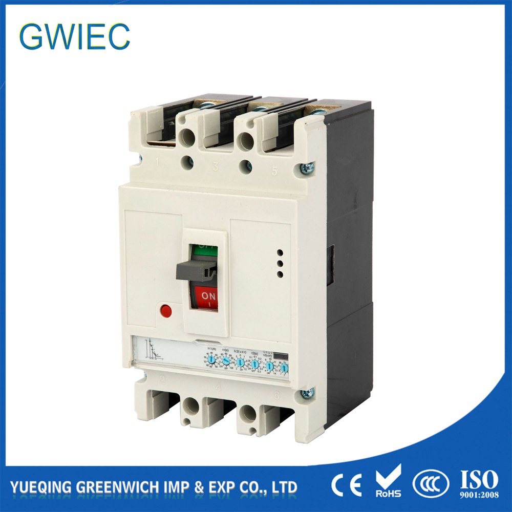
Advanced industrial applications demand precise calibration. They utilize solid-state RMS electronic trip units. These units separate the physical sensing from the rating configuration entirely. Standard thermal-magnetic units rely on bimetallic strips. Electronic units rely on microprocessors. This separation gives engineers immense flexibility.
Understanding these units requires breaking down their specific, unchangeable components.
Sensors: Manufacturers build these into the frame. They are usually air-core Rogowski CTs. They read the current continuously. They are rarely field-replaceable.
Sensor Plugs / Rating Plugs: These are interchangeable hardware components. They establish the maximum base current for the logic board.
Adjustable Dials (Ir, Ii): These dials act as fine-tuning multipliers. You adjust them to dial in the exact protection curve needed.
The calculation framework is straightforward but strictly enforced. You determine the final operational ampacity through simple multiplication. Final Ampacity equals the Sensor Plug Value multiplied by the Long-Time Delay Setting (Ir). For example, consider a 1600A frame equipped with a 1000A sensor plug. If you turn the Ir dial to 0.8, the device yields an 800A operational trip point. You mathematically force the breaker to protect an 800A wire run.
We must also address Short-Circuit Sensitivity (Ii). The Instantaneous setting (Ii) controls immediate fault clearance. It is typically a multiple of the nominal current. You often set it between 4x and 8x. Manufacturers design this specifically to tolerate high inrush currents. Heavy motors and transformers draw massive power upon startup. Proper Ii settings prevent frustrating false tripping while maintaining safety.
Interrupting Capacity (AIC) vs. Short Circuit Current Rating (SCCR)
Evaluating an industrial circuit breaker requires looking at two distinct dimensions. We must differentiate between device-level survivability and system-level compliance. Many technicians confuse AIC and SCCR during inspections. This confusion leads to severe code violations.
Amps Interrupting Capacity (AIC) defines device survivability. It is the maximum fault current the specific breaker can safely clear at a designated voltage. We measure this in kA RMS Symmetrical. If a fault exceeds this number, the device might explode. The National Electrical Code (NEC 110.9) mandates a strict rule. The AIC must always meet or exceed the available fault current at the line terminals.
Voltage caveats complicate this selection process. Breakers carry either slash ratings or straight ratings. A slash-rated device (e.g., 480Y/277V) is highly restricted. It remains compliant only for solidly grounded wye systems. The line-to-ground voltage must never exceed the lower number. Conversely, straight-rated devices (e.g., 480V) feature robust internal isolation. You require them for ungrounded or corner-grounded delta systems.
Common SCCR misconceptions persist across the industry. We must clarify them. AIC represents an isolated device metric. SCCR applies to the entire assembled panel or machinery. Upgrading a breaker's AIC does not automatically raise a panel's SCCR. The system rating remains bound by the weakest link. If busbars or terminal blocks hold a low rating, a high-AIC breaker cannot override them.
Table 1: Comparing Device vs. System Fault Ratings |
Metric | Scope | Code Reference | Primary Limitation |
AIC (Amps Interrupting Capacity) | Individual Device | NEC 110.9 | Maximum fault the single breaker can clear safely. |
SCCR (Short Circuit Current Rating) | Assembled System | NEC 409.110 | Capped by the lowest-rated component in the panel. |
Economic Evaluation: 80% vs. 100% Rated Breakers
Electrical engineers face a strict business problem during continuous load calculations. Standard NEC 240.20(a) rules force us to oversize standard breakers. We must calculate them to 125% of the continuous load. This rule dramatically inflates project expenses. You end up buying larger breakers, thicker cables, and wider conduits.
A widespread misconception surrounds 100%-rated breakers. Many assume they contain inherently "better" internal physics than 80%-rated models. This is false. The difference lies entirely in stringent UL system-level testing. The physical hardware is often identical. The certification allows you to push the breaker closer to its theoretical limits.
We must understand UL Testing and the heat sink effect. During UL489 testing, the connected copper cables act as thermal heat sinks. They pull heat away from the breaker terminals. To achieve a 100% rating, the installation must fulfill strict criteria. The breaker must sit inside a specifically sized enclosure. It strictly requires the use of 90°C-rated insulation wire. Even though you use 90°C wire, you still size the ampacity based on the 75°C column.
Chart: 80% vs. 100% Rated Breaker Installation Requirements |
Criteria | 80% Rated Breaker | 100% Rated Breaker |
Continuous Load Rating | Capped at 80% of nominal label | Full 100% of nominal label |
Wire Insulation Temp | Usually 75°C required | Strictly 90°C required |
Enclosure Specs | Standard sizing acceptable | Specific minimum volume required |
The ROI and shortlisting logic become obvious upon review. Specifying a 100%-rated breaker allows engineers to drop down a Frame Size. You might drop from a 1000AF chassis to an 800AF chassis. You drastically reduce the required copper wire gauge. Transitioning from 350 kcmil to 250 kcmil saves immense capital. It significantly lowers total installation expenses despite the premium price of the breaker itself.
Implementation Risks: Terminal Markings and 3-Phase Pitfalls
Proper procurement solves only half the puzzle. Implementation risks remain high on the factory floor. Overlooking secondary label markings leads directly to inspection failures. It also invites long-term thermal degradation. Field technicians must scrutinize every printed detail before energizing the circuit.
Wire material and torque specifications demand absolute precision. Failing to apply the exact nameplate tightening torque (Lb-In) is dangerous. It represents the leading cause of terminal overheating. Furthermore, applying 60°C wire when the label strictly bases thermal calculations on 75°C ratings invalidates the UL listing entirely. The system will run hotter than the testing model allowed.
Three-Phase amperage division errors plague many installations. Breaker ratings refer to Line Current, not Phase Current. Technicians often forget the math. Failing to account for the √3 (1.732) multiplier in Delta configurations is disastrous. Ignoring phase imbalances greater than 5% forces the most heavily loaded pole to carry excessive current. This pole will trip prematurely, shutting down the entire line.
To mitigate these risks, follow these best practices for advanced features:
Zone Selective Interlocking (ZSI): Look for this feature in heavy industrial setups. It localizes fault clearance. It prevents upstream breakers from tripping unnecessarily.
Thermal Memory: Utilize this to prevent dangerous heat accumulation. It remembers recent motor restarts and lowers the trip threshold temporarily to protect hot wiring.
Regular Torque Checks: Implement annual maintenance routines. Thermal cycling loosens lugs over time, increasing resistance.
Conclusion
Correctly specifying a moulded case circuit breaker requires precise knowledge. You must clearly distinguish between physical chassis constraints (Frame Size) and calibrated protection parameters (Amp Setting/Ir). Failing to separate these metrics leads to oversized cables and unsafe overload thresholds.
When standardizing units across a facility, prioritize solid-state electronics. Electronic trip units with interchangeable rating plugs offer superior flexibility. They allow you to scale protection without replacing the entire physical chassis. Finally, evaluate the economic benefits of 100%-rated systems for your continuous heavy loads. By doing so, you will optimize cable sizing, conserve valuable panel space, and maximize your overall installation ROI.
FAQ
Q: Can a circuit breaker be reverse-fed if it doesn't say "Line" and "Load"?
A: Yes. According to UL standards, if an MCCB lacks specific Line/Load terminal markings, it is acceptable for reverse connection applications. You can safely feed power from the bottom terminals. If the label explicitly marks them, you must follow the designated flow direction to ensure proper arc clearance.
Q: What happens if my MCCB label doesn't list an Interrupting Rating (AIC)?
A: If no AIC is printed on the label, UL defaults the device to a standard 5,000 A (5kA) interrupting capacity. This minimal rating is rarely sufficient for industrial main feeds. Always source breakers with explicitly stated AIC values matching your facility's fault current study.
Q: What do the SWD and HID markings mean on a breaker label?
A: SWD indicates the breaker is rated for Switching Duty. Inspectors approve it for regular, daily switching of fluorescent lighting up to 20A. HID means it is rated for High-Intensity Discharge lighting loads. This handles the unique inrush spikes of HID ballasts up to 50A safely.
Q: Can I swap an 800A rating plug into a 600A Frame?
A: No. While rating plugs and sensors can often be downsized, they can never exceed the maximum physical Frame Size (AF) of the breaker chassis. The internal copper busbars inside a 600A frame will melt if subjected to 800A continuous loads.


